Learn Morse Code, Clockwork Orange Style

You might have to provide your own wrist straps and eye clamps, but if you want to learn Morse code, [Seth] has a web site for you. You can get code practice using the Farnsworth method and each letter is flashed before you as it is sent, which we assume will burn it into your brain.

Why learn Morse code now? Just about all countries now have at least some no code ham licenses and many have taken code off the tests completely. However, there are still many hams that use the code even today. Why? The personal challenge is part of it and perhaps nostalgia. However, it is also true that Morse code transmitters and receivers are dead simple to build and can get through where other simple radios can’t.

Continue reading “Learn Morse Code, Clockwork Orange Style”

Complex Impedances Without The Pain

Any grizzled electronic engineer will tell you that RF work is hard. Maintaining impedance matching may be a case of cutting wires to length at lower frequencies, but into the low centimetre and millimetre wavelengths it becomes a Dark Art aided by mysterious and hugely expensive test equipment beyond the reach of mere mortals. A vector network analyser or VNA may be beyond the reach of many, but [Tomasz Wątorowski] is here to tell us about how with some resistors, mathematics, and a bit of lateral thinking its functions may be replicated with a more modestly equipped bench.

It’s not a method for the faint-hearted as the mathematics are of the variety that you probably learned as an undergraduate but let slip from your memory with thanks after the course ended. The method involves measuring the return loss both with and without a resistor of known value in series with the antenna, these figures allow the real and imaginary components of the antenna’s impedance to be calculated. There is a further piece of work though, this method doesn’t determine whether the antenna is capacitive or inductive. Repeating the measurement with either a capacitive or inductive matching network allows this to be determined, and the value of the appropriate matching component to be calculated.

If you are interested in this kind of work, start with a primer on RF design.

Complex impedance matching using scalar measurements, math and resistors

Ham Radio Company Wins Big

It is sort of the American dream: start a company in your garage and have it get crazy big. After all, Steve Jobs, Bill Gates, and even Bill Hewlett and Dave Packard did it. Seems hard to do these days, though. However, one ham radio company that has been pushing the edge of software defined radio appears to be well on the way to becoming more than its roots. FlexRadio has teamed with Raytheon to undertake a major project for the United States Air Force.

The Air Force has given Raytheon and FlexRadio $36 million to develop an HF radio based on the existing SmartSDR/Flex-6000. ARRL news reports quote FlexRadio’s CEO as saying that the investment in the military radios will pay dividends to the firm’s ham radio customers.

Continue reading “Ham Radio Company Wins Big”

Ham Radio Gets Embedded RTL-SDR

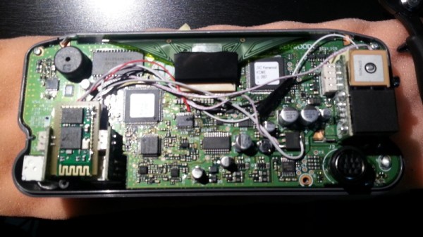
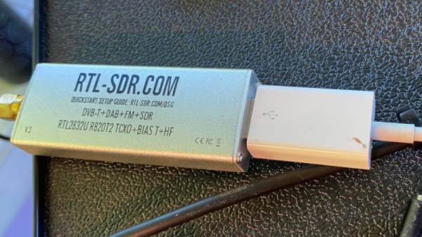
We usually think of the RTL-SDR as a low-cost alternative to a “real” radio, but this incredible project spearheaded by [Rodrigo Freire] shows that the two classes of devices don’t have to be mutually exclusive. After nearly 6 months of work, he’s developed and documented a method to integrate a RTL-SDR Blog V3 receiver directly into the Yaesu FT-991 transceiver.

The professional results of the hack are made possible by the fact that the FT-991 already had USB capability to begin with. More specifically, it had an internal USB hub that allowed multiple internal devices to appear to the computer as a sort of composite device.

Unfortunately, the internal USB hub only supported two devices, so the first order of business for [Rodrigo] was swapping out the original USB2512BI hub IC with a USB2514BI that offered four ports. With the swap complete, he was able to hang the RTL-SDR device right on the new chip’s pins.

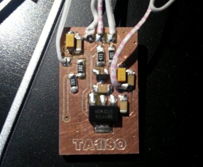
Of course, that was only half of the battle. He had a nicely integrated RTL-SDR from an external standpoint, but to actually be useful, the SDR would need to tap into the radio’s signal. To do this, [Rodrigo] designed a custom PCB that pulls the IF signal from the radio, feed it into an amplifier, and ultimately pass it to the SDR. The board uses onboard switches, controlled by the GPIO ports on the RTL-SDR Blog V3, for enabling the tap and preamplifier.

In the video after the break, you can see [Rodrigo] demonstrate his modified FT-991. This actually isn’t the first time somebody has tapped into their Yaesu with a software defined radio, though this is surely the cleanest install we’ve ever seen.

Continue reading “Ham Radio Gets Embedded RTL-SDR”

A Radio Transceiver From A Cable Modem Chipset

It’s a staple of our community’s work, to make electronic devices do things their manufacturers never intended for them. Analogue synthesisers using CMOS logic chips for example, or microcontrollers that bitbang Ethernet packets without MAC hardware. One of the most fascinating corners of this field comes in the form of software defined radios (SDRs), with few of us not owning an RTL2832-based digital TV receiver repurposed as an SDR receiver.

The RTL SDR is not the only such example though, for there is an entire class of cable modem chipsets that contain the essential SDR building blocks. The Hermes-Lite is an HF amateur radio transceiver project that uses an AD9866 cable modem chip as the signal end for its 12-bit SDR transceiver hardware with an FPGA between it and an Ethernet interface. It covers frequencies from 0 to 38.4 MHz, has 384 kHz of bandwidth, and can muster up 5W of output power.

It’s a project that’s been on our radar for the past few years, though somewhat surprisingly this is the first mention of it here on Hackaday. Creator [Steve Haynal] has reminded us that version 2 is now a mature project on its 9th iteration, and says that over 100 “Hermes-Lite 2.0” units have been assembled to date. If you’d like a Hermes-Lite of your own it’s entirely open-source, and they organise group buys of the required components.

Of course, SDRs made from unexpected components don’t have to be exotic.

Steampunk Radio Looks The Business

Radios are, by and large, not powered by steam. One could make the argument that much of our municipal electricity supply does come via steam turbines, but that might be drawing a long bow. Regardless, steampunk remains a popular and attractive aesthetic, and it’s the one that [Christine] selected for her radio build.

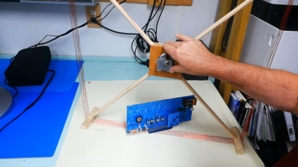
The build cribs from [Christine’s] earlier work on a VFD alarm clock, using similar tubes and driver chips to run the display. FM radio and amplification are courtesy of convenient modules. Tubes are fitted for aesthetic purposes, artfully lit with a smattering of color-changing LEDs. Perhaps the neatest touch is the use of valve handles to control tuning and volume. A stepper motor turns a series of gears, as is mandatory for any true steampunk build, and there’s even an electromagnetic actuator to make the Morse key move. To run it all, a pair of Arduino Megas are charged with handling the I/O needs of all the various systems.

It’s a fancy build that shows how far the rabbit hole you can go when chasing a particular look and feel. It’s a radio that would make a great conversation piece on any hacker’s coffee table.  If that’s not enough, consider going for a whole laptop. Video after the break. Continue reading “Steampunk Radio Looks The Business”

FM Signal Detection The Pulse-Counting Way

Compared to the simple diode needed to demodulate AM radio signals, the detector circuits used for FM are slightly more complicated. Wrapping your head around phase detectors, ratio detectors, discriminators, and quadrature detectors can be quite an exercise. There’s another demodulation method that’s not so common, but thankfully it’s also pretty easy to understand: the pulse counting detector.

As [Allan (W2AEW)] notes in the video below, pulse counting is a bit of a misnomer. Pulse counting works by generating a narrow, fixed-width square wave pulse at a set point in the received FM signal’s waveform, usually at the zero-crossing point. Since the frequency of the modulated carrier changes, the duty cycle of the resulting pulse train varies. That means there will be a fixed number of pulses, but by taking the average voltage of the pulse train, we can tease out the original audio frequency signal.

Simple in theory is often more complicated in practice, and [W2AEW] goes into some detail about those complications, such as needing to use a down-converter to make the peak-to-peak frequency deviation in the pulse train more easily detectable. As is his style, he walks us through a test circuit to prove that the theory works in practice. A simple two-transistor circuit generates the pulses at the zero-crossing point, a low-pass filter cleans up the signal, and a cheap audio amplifier reproduces the original audio. It’s a crude circuit to be sure, relying on the stray capacitance of the breadboard to work, but it proves the point and serves as a jumping-off point for further experiments – perhaps using an Arduino to count the pulses?

We always enjoy [W2AEW]’s videos and learn a lot from them. Not long ago we featured another of his videos talking about the mysteries of RF modulation; SSB, anyone?

Continue reading “FM Signal Detection The Pulse-Counting Way”