You can get electricity from just about anything. That old crystal radio kit you built as a kid taught you that, but how about doing something a little more interesting than listening to the local AM station with an earpiece connected to a radiator? That’s what the Electron Bucket is aiming to do. It’s a power harvesting device that grabs electricity from just about anywhere, whether it’s a piece of aluminum foil or a bunch of LEDs.
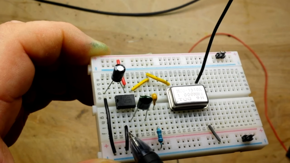
The basic idea behind the Electron Bucket is to harvest ambient radio waves just like your old crystal radio kit. There’s a voltage doubler, a rectifier, and as a slight twist, a power management circuit that would normally be found in battery-powered electronics.
Of course, this circuit can do more than harvesting electricity from ambient radio waves. By connecting a bunch of LEDs together, it’s possible to send a few Bluetooth packets around. This is pretty impressive — the circuit is using LEDs as solar cells, which normally produce about 50nA of current at 0.5V in direct sunlight. By connecting 12 LEDs in parallel and series, it manages to harvest just enough energy to run a small wireless module. That’s impressive, and an interesting entry to the Power Harvesting Challenge in this year’s Hackaday Prize.
If you have ever operated any sort of transmitting equipment, you’ve probably heard about matching an antenna to the transmitter and using the right co-ax cable. Having everything match — for example, at 50 or 75 ohms — allows the most power to get to the antenna and out into the airwaves. Even for receiving this is important, but you generally don’t hear about it as much for receivers. But here’s a question: if a 100-watt transmitter feeds a mismatched antenna and only delivers 50 watts, where did the other 50 watts go? [ElectronicsNotes] has a multi-part blog entry that explains what happens on a mismatched transmission line, including an in-depth look at voltage standing wave ratio or VSWR.
We liked the very clean graphics showing how different load mismatches affect the transmission line. We also liked how he tackled return loss and reflection coefficient.
If you are in any way connected with radio, you will have encountered the low pass filter as a means to remove unwanted harmonics from the output of your transmitters. It’s a network of capacitors and inductors usually referred to as a pi-network after the rough resemblance of the schematic to a capital Greek letter Pi, and getting them right has traditionally been something of a Black Art. There are tables and formulae, but even after impressive feats of calculation the result can often not match the expectation.
Happily as with so many other fields, in recent decades the advent of affordable high-power computing has brought with it the ability to take the hard work out of filter design, Simply tell some software what the characteristics of your desired filter are, and it will do the rest. The results are good, and anyone can become a filter designer, but as is so often the case there remains a snag. The software calculates ideal inductances and capacitances for the desired cut-off and impedance, and in selecting the closest preferred values we modify the characteristics of the result and possibly even ruin our final filter. So it’s worth taking a look at the process here, and examining the effect of tweaking component values in this way.
The filter we’re designing is simple enough, a 5th-order Bessel filter, and the software is the easy-to-use QUCS package on an Ubuntu Linux machine. Plug in the required figures and it spits out a circuit diagram, which we can then simulate to show a nice curve with a 3dB point right on 30MHz. It’s an extremely idealised graph, and experience has taught me that real-world filters using these designs have a lower-frequency cut-off point, but for our purposes here it’s a good enough start.
As previously mentioned, the component values are not preferred ones from a commercially available series, so I can’t buy them off the shelf. I can wind my own inductors, but therein lies a whole world of pain of its own and I’d rather not go there. RS, Mouser, Digikey, Farnell et al exist to save me from such pits of electronic doom, why on earth would I do anything else but buy ready-made?
So each of the components in the above schematic needs moving up or down a little way to a preferred value. What effect will that have on the performance of my filter? Changing each value and re-running the simulation shows us the graph changing subtly each time, and it can sometimes be a challenge to adjust them without destroying the filter entirely. Particularly with the higher-order filters with more components in the network you can observe the effect of individual components on the gradient at different parts of the graph, but as a rule of thumb making values higher reduces the cut-off frequency and making them lower increases it. In my case I always pick higher values for that reason: my nearest harmonic I wish to filter is at double the frequency so I have quite some headroom to play with.
Having replaced my component values with preferred ones I can run the simulation again, and I can see from the resulting graph that I’ve been quite fortunate in not damaging its characteristics too much. As expected the cut-off frequency has shifted up a little, but the same curve shape has been preserved without any ripples appearing or it being made shallower.
If I were using this filter with a real transmitter I would ensure that I designed it with a cut-off at least a quarter higher than the transmission frequency. In practice I find the cut-off to be sharper and lower than the simulation leads one to expect, and for example, were I to use this one with a 30 MHz transmitter I’d find it attenuated the carrier by more than I’d consider acceptable. It must also be admitted that changing the component values in this way will also change the impedance of the filter from the calculated 50 ohms, however in practice this does not seem to be significant enough to cause a problem as long as the value changes are modest.
We haven’t made this filter, but in the past we’ve featured another one I did make, and by coincidence it was in the same frequency range. When I wrote a feature on automating oscilloscope readings, the example I used was the characterisation of a 7th-order 30 MHz low-pass filter. It might even be one of the ones in the header image, pulled from my random bag of filter boards for the occasion.
If you have even the slightest interest in microwave electronics and radar, you’re in for a treat. The Signal Path is back with another video, and this one covers the internals of a simple 24-GHz radar module along with some experiments that we found fascinating.
The radar module that [Shahriar] works with in the video below is a CDM324 that can be picked up for a couple of bucks from the usual sources. As such it contains a lot of lessons in value engineering and designing to a price point, and the teardown reveals that it contains but a single active device. [Shahriar] walks us through the layout of the circuit, pointing out such fascinating bits as capacitors with no dielectric, butterfly stubs acting as bias tees, and a rat-race coupler that’s used as a mixer. The flip side of the PCB has two arrays of beam-forming patch antennas, one for transmit and one for receive. After a few simple tests to show that the center frequency of the module is highly variable, he does a neat test using gimbals made of servos to sweep the signal across azimuth and elevation while pointing at a receiving horn antenna. This shows the asymmetrical nature of the beam-forming array. He finishes up by measuring the speed of a computer fan using the module, which has some interesting possibilities in data security as well as a few practical applications.
[Mr. Carlson] bought a Globe Scout Model 40A ham radio transmitter at a hamfest. The 40A was a grand old transmitter full of tubes, high voltage, and a giant transformer. It is really interesting to see how much things have changed over the years. The transmitter is huge but has comparatively few parts. You needed a crystal for the frequency you wanted to talk. There were two little modules that were precursors to hybrid circuits (which were precursors to ICs) that were often called PECs or couplates (not couplets) but other than those, it is all tubes and discrete components beautifully wired point-to-point.
The really surprising part, though, is the back panel. There’s a screw terminal to drive the coil of an external coaxial relay that has line voltage on it. There’s also a plug on the back with exposed terminals that has plate voltage on it which is considerable. In the 1950s, you assumed people operating equipment like this would be careful not to touch exposed high voltage.
There are a multitude of radio shields for the Arduino and similar platforms, but they so often only support one protocol, manufacturer, or frequency band. [Jan Gromeš] was vexed by this in a project he saw, so decided to create a shield capable of supporting multiple different types. And because more is so often better, he also gave it space for not one, but two different radio modules. He calls the resulting Swiss Army Knife of Arduino radio shields the Kite, and he’s shared everything needed for one on a hackaday.io page and a GitHub repository.
Supported so far are ESP8266 modules, HC-05 Bluetooth modules, RFM69 FSK/OOK modules, SX127x series LoRa modules including SX1272, SX1276 and SX1278, XBee modules (S2B), and he claims that more are in development. Since some of those operate in very similar frequency bands it would be interesting to note whether any adverse effects come from their use in close proximity. We suspect there won’t be because the protocols involved are designed to be resilient, but there is nothing like a real-world example to prove it.
With the incredibly low cost of software defined radio (SDR) hardware, and the often zero cost of related software, there’s never been a better time to get into the world of radio. If you’ve got $30 burning a hole in your pocket, you’re good to go. But as with any engrossing hobby that’s cheap to get into, you run the risk of going overboard eventually.
For example, if the radio gear inside your car approaches parity with the Kelly Blue Book value of said vehicle, you may have been bitten by the radio bug. In the video after the break, [Corrosive] gives us a tour of his antenna festooned Hyundai Accent, that features everything he needs to receive and analyze a multitude of analog and digital radio signals on the go.
He starts with the roof of the car, which is home to five whip antennas (not counting the one from the factory installed AM/FM radio) and two GPS receivers. The ones on the rear of the car feed down into the trunk, where a bank of Nooelec NESDR RTL-SDR receivers will live in a USB hub. He’s only got one installed for test purposes, but he’ll need more for everything he’s got planned. Also riding in the back is a BCD780XLT scanner, which he got cheap on eBay thanks to the fact it had a dead display.
Luckily, where [Corrosive] is going, he won’t need displays. The SDR receivers and the scanner are all controlled from the driver’s seat by way of a Windows 10 tablet. This runs the ProScan software that provides a virtual interface to the BCD780XLT, as well as various SDR interfaces. He’s also got Gpredict for tracking satellites and ADS-B programs like Virtual Radar.
The car’s head unit has been replaced by a rooted Android entertainment system which supports USB host mode. [Corrosive] says it isn’t hooked up yet, but in the future the head unit is going to get its own SDR receiver so he can run programs like RF Analyzer right in the dashboard. We’re willing to bet that this will be the only car in the world that has both a waterfall display and the “Check Engine” light on at the same time.