While Chevrolet’s innovative electric hybrid might officially be headed to that great big junkyard in the sky, the Volt will still live on in the hearts and minds of hackers who’d rather compare amp hour than horsepower. For a relatively low cost, a used Volt offers the automotive hacker a fascinating platform for upgrades and experimentation. One such Volt owner is [Katie Stafford], who’s recently made some considerable headway on hacking her hybrid ride.
 In an ongoing series on her blog, [Katie] is documenting her efforts to add new features and functions to her Volt. While she loves the car itself, her main complaint (though this is certainly not limited to the Volt) was the lack of tactile controls. Too many functions had to be done through the touch screen for her tastes, and she yearned for the days when you could actually turn a knob to control the air conditioning. So her first goal was to outfit her thoroughly modern car with a decidedly old school user interface.
Like most new cars, whether they run on lithium or liquefied dinosaurs, the Volt makes extensive use of CAN bus to do…well, pretty much everything. Back in the day it only took a pair of wire cutters and a handful of butt splice connectors to jack into a car’s accessory systems, but today it’s done in software by sniffing the CAN system and injecting your own data. Depending on whether you’re a grease or a code monkey, this is either a nightmare or a dream come true.
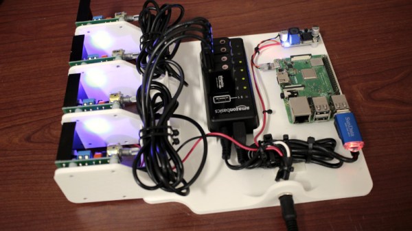
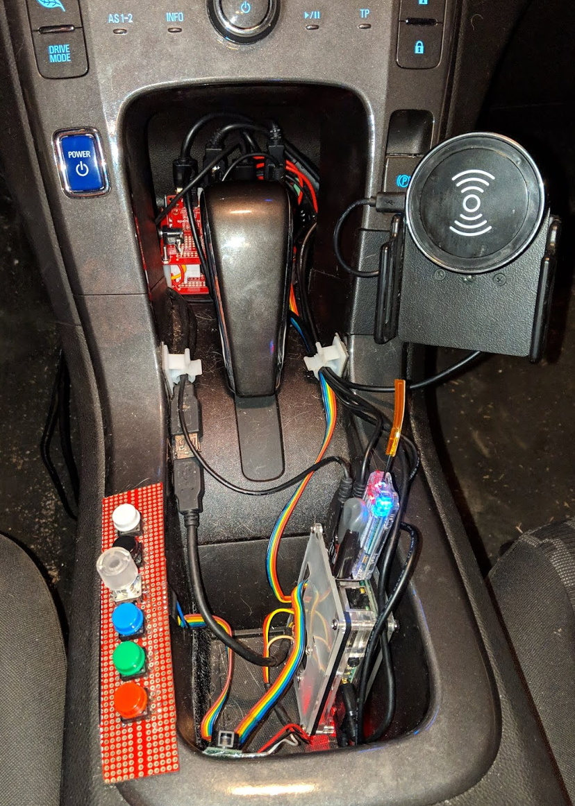
Luckily [Katie] is more of the latter, so with the help of her Macchina M2, she was able to watch the data on the CAN bus as she fiddled with the car’s environmental controls. Once she knew what data needed to be on the line to do things like turn on the fan or set the desired cabin temperature, she just needed a way to trigger it on her terms. To that end, she wired a couple of buttons and a rotary encoder to the GPIO pins of a Raspberry Pi, and wrote some code that associates the physical controls with their digital counterparts.
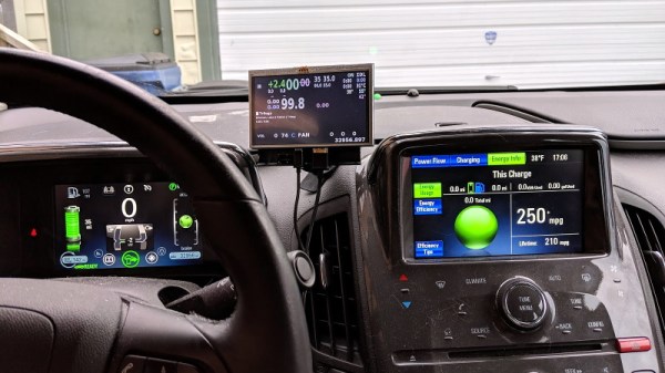
That’s all well and good when you need to mess around with the AC, but what’s the Pi supposed to do the rest of the time? [Katie] decided a small HDMI display mounted to the dash would be a perfect way for the Raspberry Pi to do double duty as information system showing everything from battery charge to coolant temperature. It also offers up a rudimentary menu system for vehicle modifications, and includes functions which she wanted quick access to but didn’t think were necessarily worth their own physical button.
In the video after the break, [Katie] walks the viewer through these modifications, as well as some of the other neat new features of her battery powered bow tie. What she’s already managed to accomplish without having to do much more than plug some electronics into the OBD-II port is very impressive, and we can’t wait to see where it goes from here.
Today there are simply too many good electric cars for hybrids like the Chevy Volt and its swankier cousin the Cadillac ELR to remain competitive. But thanks to hackers like [Katie], we’re confident this isn’t the last we’ve seen of this important milestone in automotive history.
Continue reading “Juicing Up The Chevy Volt With Raspberry Pi”