A few months ago we were lucky to get the scoop on a new Raspberry Pi a few days before it was officially announced. This model ended up being the Raspberry Pi Model B+, with improvements that included more USB ports, not-dumb mounting holes, more GPIOs, and a decent microSD card connector. Today, we’re proud to leak another revision to the Raspberry Pi ecosystem – the Raspberry Pi Model A+
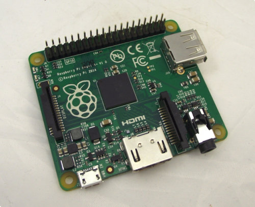
There really aren’t many details for this new revision of the Raspi, but we can make some educated guesses. The new model features the same not-dumb mounting holes as the B+, 58mm wide by 49mm wide. All the ports are moved to two sides of the board, and the analog audio and video are combined into one 3.5mm jack. Like the normal Model A, this one doesn’t have Ethernet and only one USB port, but the improvements seen from the B to the B+ are still there: a good microSD card socket is on the back, and the 40-pin GPIO header replaces the old 26-pin header. There’s no word if the A+ will feature a RAM upgrade – when the Model B was ramping up production The Foundation decided to bump the RAM up to 512MB. This could happen with the A+, but we’re not holding our breath.
There’s no word when the A+ will be announced, or when it will start shipping. The educated guess would say tomorrow morning, with an analysis of how much power this thing consumes a week after it starts shipping.