Although both a SEM and a TEM are electron microscopes, their working principles and images are very different. Whereas an SEM uses secondary electrons ejected after bombarding a sample’s surface with primary electrons, a TEM works more like an X-ray machine, with a sensor placed behind the sample to record primary electrons after they pass through said sample. It is, however, possible to turn a SEM into a TEM with some creativity, as [ProjectsInFlight] recently did with his SEM.
We previously covered how the SEM in the video was saved from being scrapped and subsequently revived, and now it is getting a pretty nice upgrade. That said, this SEM to TEM change isn’t anything new, with so-called STEM imaging having been possible for ages using a rather simple reflecting adapter. The problem here is that such adapters cost enough to make you dread filing a budget request, yet they are simple enough that you might be able to DIY one.
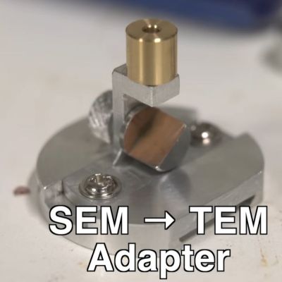
The main concern with the DIY adapter was clearance between the sample holder and the fragile components inside the chamber. This turned out to be a hair under 14 mm (0.55″), giving not a lot of space to work with, but that was relative to the standard bulky sample holder. With a thinner sample plate machined out of aluminum, significantly more space became available, including for the primary electron mirror and shield for the secondary electrons.
Some more lathe, milling, and tapping work later, the entire sample holder came together. During testing a hack was implemented to enable adjusting the mirror angle while in the evacuated vacuum chamber so that the adapter could be dialed-in. Subsequently, a first sample was imagined in the form of gold nanoparticles, which revealed a leaky secondary electron shield due to bypassing.
Further testing revealed that the shield needed to extend much higher to meaningfully block secondary electrons, after which the TEM image massively improved. Subsequently, a previously expired mosquito graciously donated its wings to science, with TEM imaging clearly revealing the delicate structures within these wonders of evolutionary design.
The next challenge will be to TEM image biological cells, which require substantial preparation.
This isn’t the first STEM converter we’ve seen. The SEM has a long checkered history that we’ve talked about before, too.
Continue reading “Converting A Scanning Electron Microscope Into A TEM Is Surprisingly Easy”