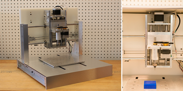
While cheap hobby CNC mills and routers are great machines that allow you to build things a 3D printer just can’t handle, they do have their limitations. They’re usually powered by a Dremel or other rotary tool, so speed control of the spindle via Gcode is nigh impossible. They’re also usually built with a piece of plywood as the bed – cheap, but not high on repeatability. The Nomad CNC mill fixes these problems, and manages to look good and be pretty cheap, to boot.
Instead of using a Dremel or other rotary tool to cut materials, the Nomad team is using a brushless DC motor connected to a real spindle. With a few certain motors, this allows for closed loop control of the spindle; Sending S4000 Gcode to the mill will spin the spindle at 4000 RPM, and S6000 runs the spindle at 6000 RPM, whether it’s going through foam or aluminum. This is something you just can’t do with the Dremel or DeWalt rotary tools found in most desktop mills and routers.
Along with a proper spindle, the Nomad also features homing switches, a tool length probe, and a few included fixtures that make two-sided machining – the kind you need it you’re going to machine a two-layer PCB – possible, and pretty simple, too. The softwares controlling the mill are Carbide Motion and MeshCAM, a pretty popular and well put together CNC controller. Of course the mill itself speaks Gcode, so it will work with open source CNC software.
It’s all a very slick and well put together package. Below you can find a video of the Nomad milling out a Hackaday logo.
Continue reading “Finally, A Desktop CNC Machine With A Real Spindle”


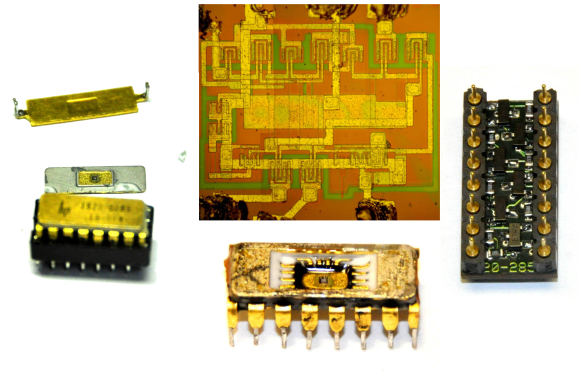 [Matthew] got himself into a real pickle. It all started when he was troubleshooting a broken Hewlett Packard 8007A pulse generator. While trying to desolder one of the integrated circuits, [Matthew] accidentally cracked it. Unfortunately, the chip was a custom HP Pulse shaper IC – not an easy part to source by any means. That broken chip began a 5 year mission: to explore strange new repair methods. To seek out new life for that HP 8007A.