[James] builds all sorts of robots and superhero costume replicas at home, so he is always searching for a better way to get consistent results when using his vacuum table. A lot of people use their oven or exposed heating coils from electric frying pans to warm the plastic sheets, but [James] wasn’t really interested in going down that route. He cites that he would rather not heat plastic in the oven where he cooks his food, nor is he really keen on the idea of exposed heating elements.
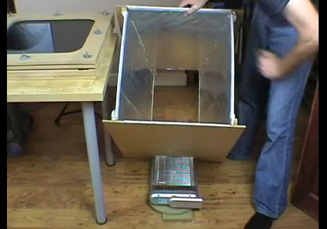
Instead, he opted for a slightly pricier, though completely reasonable setup that produces consistent results every time. Most of the forming table was built using MDF sheeting, as you can see in the video below. His heating apparatus was the most expensive part of the rig, since it’s an off the shelf quartz-based room heater. He lays the heater on its back side, and directs the heat up through an MDF frame using aluminum foil as a reflector. The plastic sheeting mounted at the top heats evenly, and in no time, he has a perfectly vacuum formed prop that is ready to be painted.
Sure, it might cost a bit more than some other vacuum formers we’ve looked at before, but spending a bit more up front to get consistent results is well worth it if you ask us.
Continue reading “How To Build A Vacuum Form Table That Gets It Right Every Time”