You can salvage lithium 18650 cells from all sorts of modern gadgets, from disposable vapes to cordless power tools. The tricky part, other than physically liberating them from whatever they are installed in, is figuring out if they’re worth keeping or not. Just because an 18650 cell takes a charge doesn’t necessarily mean it’s any good — it could have vastly reduced capacity, or fail under heavy load.
If you’re going to take salvaging these cells seriously, you should really invest in a charger that is capable of running some capacity tests against the cell. Or if you’re a bit more adventurous, you can build this “Battery Health Monitor” designed by [DIY GUY Chris]. Although the fact that it can only accept a single cell at a time is certainly a limitation if you’ve got a lot of batteries to go though, the fact that it’s portable and only needs a USB-C connection for power means you can take it with you on your salvaging adventures.
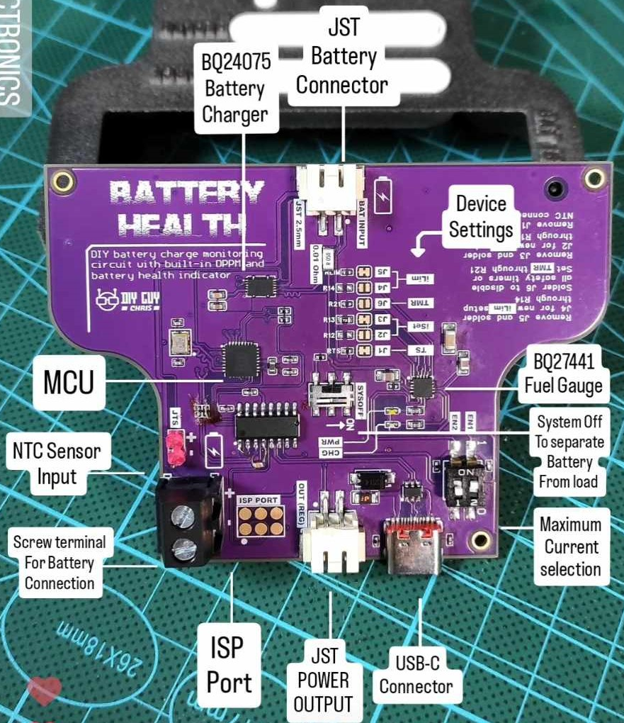 The key to this project is a pair of chips from Texas Instruments. The BQ27441 is a “Fuel Gauge” IC, and is able to determine an 18650’s current capacity, which can be compared to the cell’s original design capacity to come up with an estimate of its overall health. The other chip, the BQ24075, keeps an eye on all the charging parameters to make sure the cell is being topped up safely and efficiently.
With these two purpose-built chips doing a lot of the heavy lifting, it only takes a relatively simple microcontroller to tie them together and provide user feedback. In this case [DIY GUY Chris] has gone with the ATmega328P, with a pair of addressable WS2812B LED bars to show the battery’s health and charge levels. As an added bonus, if you plug the device into your computer, it will output charging statistics over the serial port.
The whole project is released under the MIT license, and everything from the STL files for the 3D printed enclosure to the MCU’s Arduino-flavored firmware is provided. If you’re looking to build one yourself, you can either follow along with the step-by-step assembly instructions, or watch the build video below. Or really treat yourself and do both — you deserve it.
If your battery salvaging operation is too large for a single-cell tester, perhaps it’s time to upgrade to this 40-slot wall mounted unit.
Continue reading “Handheld 18650 Analyzer Scopes Out Salvaged Cells”