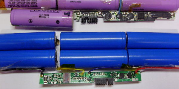
Lithium-Ion batteries are finicky little beasts. They can’t be overcharged, overdischarged, overheated, or even looked at funny without bursting into flames. Inside any laptop battery pack, a battery charge controller keeps watch over all the little cells, and prevents them from getting damaged.
Of course, any “smart” device will sometimes make the wrong choices, and then it’s up to us to dig inside its brains and fix it. When [Viktor] got a perfectly good battery pack with a controller that refused to charge the batteries, he started off on what would become an epic journey into battery controllers, and the result is not just a fixed battery, but a controller-reprogramming tool, software, and three reversed controller chips so far.
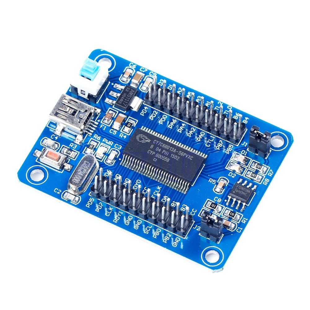 Battery controller chips speak SMBus, and [Viktor] started out by building a USB-SMBus tool. It’s a clever use of a cheap eBay development board for a Cypress CY7C68013A USB microcontroller. Flashed with [Viktor]’s firmware and running his software on the host computer, a SMBus scan is child’s play.
The rest of the story is good old-fashioned hacking: looking for datasheets, reading industry powerpoints, taking wild guesses, googling for passwords, and toggling the no-connect pins while booting the controllers up. We’re not going to argue with results: the bq8030, R2J240, and M37512 controllers have all given up their secrets, and tools to program them have been integrated into [Viktor]’s SMBusb tool.
In short, this is one of the nicest hard-core hacks we’ve seen in a while. Kudos [Viktor]! And thanks for the SMBus tool.