Looking for a quick way to desolder those pesky DIP chips? Check out this handy little tip in the video after the break. [Clay Cowgill] shows you the easy way to do it.
Normally, before you desolder a Dual In-line Package (DIP) chip, you have a decision to make: Are you interested in saving the chip or the PCB? The repeated cycles of heating and reheating the PCB while using solder wick, or even a “solder sucker”, can cause a real problem for the PCB. You run the risk of delamination of the PCB traces. Some phenolic based PCBs can barely handle one extra heat cycle, while as a top-quality PCB might be fine with 4 or even 6 rework attempts – but we’ve lifted off tracks with less. And all that thermal stress isn’t exactly the best thing for the chip itself. You risk ending up with a dud.
The other trick commonly used is to cut the pins of the DIP and then you can treat each pin as a single through hole part – and that is generally less aggressive to the PCB, there by saving your board, but destroying the chip.
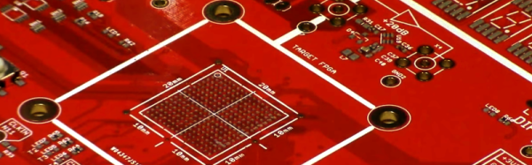
In the video [Clay Cowgill] is using a Hakko 850 hot air rework station to desolder parts from an Atari 130EX motherboard. He’s able to effortlessly remove the chips, and save the PCB, all without applying and re-applying heat over and over again. That’s something we’ve seen before – the interesting part is where he then uses the air flow to blow the through hole openings clean – making for some of the fastest and cleanest DIP removal we’ve ever seen without using a dedicated desoldering gun.
[Thanks [wblock] via Eevblog]