[ossum] had a stack of Amazon and Shapeways credits lying around after winning a few competitions. He had this dream of building an R/C car for a while, and decided now was the time. After ordering all the needed parts from Amazon, he made an extremely nice model of the car in Fusion 360. The CAD model is a great learning resource. If you want to learn how to use reference photos, parts, and more to build a detailed and useful CAD model we recommend downloading it as a Fusion archive and scrubbing through the timeline to see how he did it.
Some of the parts were sent off for laser cutting. Others were 3D printed. The rest he made himself. Thanks to his model, they all went together well. You can see his R/C rod racing in the video after the break.
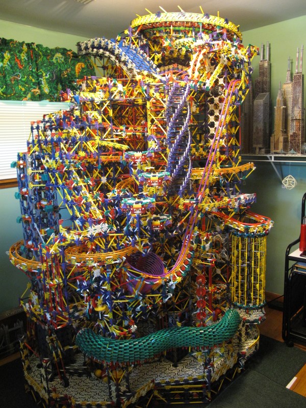
Following one’s passion can lead to amazing results. Sometimes this results in technological marvels; other times, one marvels at the use of the technology. An exemplary display of the latter is The Citadel.
Over the course of three years, redditor [Shadowman39] pieced together this monstrous K’nex structure. With over 17 different paths(!), 45 different elements, and over 40,000 parts, you would expect some meticulous planning to go into its construction — but that’s not the case! [Shadowman39] assembled it largely on the fly with only a few elements needing to be sketched out and only the main elevator proving to be troublesome. Three motors power the structure — one for the main elevator, one for the smaller lifts on the bottom, and one for the release gates.
This is an absolute leviathan hobby project. To satiate the obvious curiosity of anyone who stumbles across this picture, its intricacies can be seen in the video:
Necessity is the mother of invention, but cheap crap from China is the mother of reverse engineering. [Michael] found a very, very cheap toy quadcopter in his local shop, and issued a challenge to himself. He would reverse engineer this quadcopter’s radio protocol. His four-post series of exploits covers finding the right frequency for the radio, figuring out the protocol, and building his own remote for this cheap toy.
[Michael] was already familiar with the capabilities of these cheap toys after reading a Hackaday post, and the 75-page, four language manual cleared a few things up for him. The ‘Quadro-Copter’ operated on 2.4GHz, but did not give any further information. [Michael] didn’t know what channel the toy was receiving on, what data rate, or what the header for the transmission was. SDR would be a good tool for figuring this out, but thanks to Travis Goodspeed, there’s a really neat trick that will put a 2.4GHz nRF24L01+ radio into promiscuous mode, allowing [Michael] to read the transmissions between the transmitter and quadcopter. This code is available on [Michael]’s github.
A needle in an electromagnetic haystack was found and [Michael] could listen in on the quadcopter commands. The next step was interpreting the ones and zeros, and with the help of a small breakout board and soldering directly to the SPI bus on the transmitter, [Michael] was able to do just that. By going through the nRF24 documentation, he was able to suss out the pairing protocol and read the stream of bytes that commanded the quadcopter.
What [Michael] was left with is a series of eight bytes sent in a continuous stream from the transmitter to the toy. These bytes contained the throttle, yaw, pitch, roll, and a ‘flip’ settings, along with three bytes of ‘counters’ that didn’t seem to do anything. With that info in hand, [Michael] took an Arduino Nano, an nRF04L01+ transceiver, and a Wii nunchuck to build his own transmitter. If you’re looking for a ‘how to reverse engineer’ guide, it generally doesn’t get better than this.
You can check out a video of [Michael] flying his Wiimoted quadcopter below.
[Rulof] never ceases to impress us with what he comes up with and how he hacks it together. Seriously, how did he even know that the obscure umbrella part he used in this project existed, let alone thought of it when the time came to make a magnet mount? His hack this time is a real world, tabletop race track made for his little brother, and by his account, his brother is going crazy for it.
His race track is on a rotating table and consists of the following collection of parts: a motor, bicycle wheel, casters from a travel bag, rubber bands (where did he get such large ones?), toy car and steering wheel from his brother, skateboard wheels, the aforementioned umbrella part and hard drive magnets. In the video below we like how he paints the track surface by holding his paint brush fixed in place and letting the track rotate under it.
From the video you can see the race track has got [Rulof] hooked. Hopefully he lets his brother have ample turns too, but we’re not too sure. Some additions we can imagine would be robotics for the obstacles, lighting, sounds and a few simulated explosion effects (puffs of flour?).
Fallout logic. This is literally called Fallout logic. This is far more confusing than it should be.
Fallout 4, the latest tale of post-apocalyptic tale of wasteland wanderers, got its latest DLC yesterday. This add-on, Contraptions Workshop, adds new objects and parts to Fallout 4‘s settlement-building workshop mechanic. This add-on brings more building pieces, elevators, and most importantly logic gates to Commonwealth settlements.
The Fallout logic gates are used in conjunction with electric generators, lights, and automated sentries used to build settlements. Although a simple NAND would do, there are several types of logic gates including AND, OR, XOR, NOT, NAND, NOR, and XNOR.
The in-game explanation for these gates is very, very weird. AND, OR, and XOR “transmit power or not depending on the combination of power to their inputs”. NOT, NAND, NOR, and XNOR are apparently different, “only transmitting power if their inputs are connected directly to the output of other logic gates”. The reason for this arbitrary distinction between different sets of gates is currently unknown except to a few programmers and project leaders at Bethesda. It should be noted {AND, OR, XOR} is not functionally complete.
With implementations of logic gates in video games comes some very interesting if useless applications. Already Fallout 4 has light boxes, allowing for huge animated billboards. Fallout speakers, the wasteland’s equivalent of Minecraft’s note block, can be used to play simple melodies. You can do anything with a NAND, so we would expect automated, sequenced versions of animated billboards and monophonic synthesizers to appear in short order.
Functional completeness can add a lot to a game. Since Minecraft added redstone logic to the game, we’ve seen some very, very impressive block-based builds. The Minecraft CPU generally regarded as being the first, most complete CPU took about three months to design and build. This build didn’t use later additions to the redstone toolbox like repeaters, pistons, and the now-cheaty command blocks.
There’s a war on, and while this over-the-top water blaster is certainly an escalation in the Water Wars arms race, that’s not the war we’re referring to. We’re talking about the Documentation War. Hackers, you’re on notice.
If you want to see how a project should be documented, look no further than [Tim]’s forum posts over at WaterWar.net. From the insanely detailed BOM with catalog numbers and links to supplier websites, to scads of build photos with part number callouts, to the finely detailed build instructions, [Tim] has raised the stakes for anyone that documents any kind of build.
And that’s not even touching on the merits of the blaster itself, which has air and water tanks plumbed with every conceivable valve and fitting. There’s even an inline stream straightener made of bundled soda straws to keep the flow as laminar as possible. It looks like [Tim] and his colleagues are obsessed with launching streams of water as far as possible, and although bad weather has prevented an official measurement so far, from the video below it sure looks like he’s covering a huge distance with a stream that stays mostly intact to deliver the full blast to its intended target without losing a drop.
For as much fun as amped-up water guns appear to be, we haven’t seen too many grace these pages before. Going way back we covered a DIY super-soaker. For something much less involved than [Tim’s] masterpiece, you can pull together this pressurized water pistol in an afternoon.
The must-have toy of the moment last winter was the “Hoverboard”. We all probably secretly wished them to be the boards from the Back to the Future series of films made real, but the more achievable reality is a self-balancing scooter somewhat akin to a miniature Segway. It seemed every child wanted one, schools banned them, and there was a media frenzy over some of the cheaper models that lacked protection circuitry for their li-ion batteries and thus had a tendency for self-incineration.
[Drew Dibble] is interested in the Power Racing Series (PRS), in which toy electric cars are souped up for competition. Casting around for a source of cheap and relatively powerful motors he lit upon the self-balancing scooters, and waited on Craigslist for the inevitable cast-offs. His resulting purchase had two 350W brushless hub motors and all the associated circuit boards for motor control, gyroscope, and oddly a Bluetooth speaker. The motor control board received an unknown two-wire digital feed from the scooter’s control board, so he set to work investigating its protocol. His write-up of how he did it is an interesting primer in logic line detective work.
Hooking up his logic analyzer he was quickly able to rule out the possibility of the control signal being PWM because all signals followed the same timing. Both lines had data so he was able to rule out I2C, for in that case one line would carry a clock. He was therefore left with a serial line, and taking the 38 microsecond timing interval, he was able to calculate that it had a rather unusual bitrate of 26315 BPS. Each packet had a multiple of 9 bits so he either had 9-bit or 8-bit with parity, and trying all possible parity schemes resulted in parity errors. Therefore the boards used a highly unusual 9-bit non-standard bitrate serial port. Some experimentation led him to an Arduino library, and he was able to get some movement from his motors. Some clever timing detective work later and he could make them move at will, success!


 If you want to see how a project should be documented, look no further than [Tim]’s forum posts over at WaterWar.net. From the insanely detailed BOM with catalog numbers and links to supplier websites, to scads of build photos with part number callouts, to the finely detailed build instructions, [Tim] has raised the stakes for anyone that documents any kind of build.