Building A Modern Retro Console

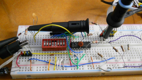
There are a few dozen classic re-imaginings of classic game consoles, using hardware ranging from the ATMegas of the Uzebox to everyone’s favorite, stuffing some ROMs on a Raspi and calling it a day. You don’t necessarily learn anything doing that, which puts [Mike]’s custom game console head and shoulders above the rest.

The build started off as a plan for a Z80 computer with a dual ATMega GPU. He progressed far enough in the design where it would have been a masterpiece, but the inability to mill double-sided boards at home killed the design. Plans then moved on to an FPGA, then to an ATMega with the Analog Device AD725 PAL/NTSC encoder chip. That idea had a similar architecture to the Uzebox, but [Mike] wanted more power. He eventually settled on a PIC32 with the AD725.

This setup was capable of pumping out some impressive graphics, but for moving bits to a screen, you need DMA. [Mike] ran into a problem where the DMA timer runs at a maximum rate of 3.7 MHz. It’s a problem documented in a few projects, leading [Mike] to change his plan once again, this time to the STM32F4.

The bugs are worked out, and now [Mike] can stream a whole lot of pixels to a screen while still having some processing power left over to play a game. It’s a project that’s more than a year and a half old at this point, and so far he’s learned a lot.

Reverse Engineer Then Drive LCD With FPGA

Fans of [Ben Heck] know that he has a soft spot for pinball machines and his projects that revolve around that topic tend to be pretty epic. This is a good example. At a trade show he saw an extra-wide format LCD screen which he thought would be perfect on a pinball build. He found out it’s a special module made for attaching to your car’s sun visor. The problem is that it only takes composite-in and he wanted higher quality video than that offers. The solution: reverse engineer the LCD protocol and implement it in an FPGA.

This project is a soup to nuts demonstration of replacing electronics drivers; the skill is certainly not limited to LCD modules. He starts by disassembling the hardware to find what look like differential signaling lines. With that in mind he hit the Internet looking for common video protocols which will help him figure out what he’s looking for. A four-channel oscilloscope sniffs the signal as the unit shows a blue screen with red words “NO SIGNAL”. That pattern is easy to spot since the pixels are mostly repeated except when red letters need to be displayed. Turns out the protocol is much like VGA with front porch, blanking, etc.

With copious notes about the timings [Ben] switches over to working with a Cyclone III FPGA to replace the screen’s stock controller. The product claims 800×234 resolution but when driving it using those parameters it doesn’t fill the entire screen. A bit more tweaking and he discovers the display actually has 1024×310 pixels. Bonus!

It’s going to take us a bit more study to figure out exactly how he boiled down the sniffed data to his single color-coded protocol sheet. But that’s half the fun! If you need a few more resources to understand how those signals work, check out one of our other favorite FPGA-LCD hacks.

Continue reading “Reverse Engineer Then Drive LCD With FPGA”

The Giant Flip-Dot Display At CES

Flip-dot displays are grand, especially this one which boasts 74,088 pixels! I once heard the hardware compared to e-ink. That’s actually a pretty good description since both use a pixel that is white on one side and black on the other, depend on a coil to change state, and only use electricity when flipping those bits.

What’s remarkable about this is the size of the installation. It occupied a huge curving wall on the ooVoo booth at 2015 CES. We wanted to hear more about the hardware so we reached out to them they didn’t disappoint. The ooVoo crew made time for a conference call which included [Pat Murray] who coordinated the build effort. That’s right, they built this thing — we had assumed it was a rental. [Matt Farrell] recounts that during conception, the team had asked themselves how an HD video chat for mobile company can show off display technology when juxtaposed with cutting edge 4k and 8k displays? We think the flip-dot was a perfect tack — I know I spent more time looking at this than at televisions.

Join us after the break for the skinny on how it was built, including pictures of the back side of the installation and video clips that you have to hear to believe.

Continue reading “The Giant Flip-Dot Display At CES”

Generating Video With The PIC

[bekeband] recently came across an old industrial monitor. It’s small, monochrome, has a beautiful green phosphor, and does not accept a composite signal. Instead, there’s a weird TTL input with connectors for horizontal sync, vertical sync, and video. Intrigued, [bekeband] brought it home and started working on a project that would drive this monitor. He succeeded, and with a chip we don’t see much of on the Hackaday tips line: a 16-bit PIC.

The project uses the dsPIC30F3011, a strange little 16-bit PIC in a 40-pin package. The board for this build actually comes from an earlier build, and after connecting the horizontal sync, vertical sync, and video to this tiny board, [bekeband] started writing some code.

There are two programs written for this board. The first is a static image tester that displays a single image on the CRT. The second is one that displays a simple animation, in this case, a horse running in place. It’s not the fanciest project, but it does work, and even though [bekeband] isn’t using a high-speed ARM, he is getting a reasonably high resolution out of this chip.

Video below.

Continue reading “Generating Video With The PIC”

Ultimate Oscilloscope Hack – Quake In Realtime

[Pekka] set himself up with quite the challenge – use an oscilloscope screen to display Quake in realtime – could it even be done? Old analog scope screens are just monochromatic CRTs but they are designed to draw waveforms, not render graphics.

Over the years Hackaday has tracked the evolution of scope-as-display hacks: Pong, Tetris, vector display and pre-rendered videos. Nothing that pushed boundaries quite like this.

[Pekka]’s solution starts off the same as many others, put the scope in X-Y mode and splice up your headphone cable – easy. He then had to figure out some way to create an audio signal that corresponded to the desire image. The famous “Youscope” example demos this, but that demo is pre-rendered. [Pekka] wanted to play Quake in realtime on the scope itself, not just watch a recording.

With only so much bandwidth available using a soundcard, [Pekka] figured he could draw a maximum of about a thousand lines on screen at a time. The first headache was that all of his audio cards had low-pass filters on them. No way around it, he adjusted his ceiling accordingly. ASIO and PortAudio were his tools of choice to create the audio on the fly from a queue of XY lines given.

To tell his audio engine what lines to draw, he solicited Darkplaces – an open source Quake rendering engine – and had it strip polygons down to the bare minimum. Then he had to whip out the digital hedge trimmers and continue pruning. This writeup really cannot do justice to all the ingenious tricks used to shove the most useful data possible through a headphone jack. If this kind of thing interests you at all, do yourself a favor and check out his well-illustrated project log.

In the end [Pekka] was not entirely happy with the results. The result is playable, but only just barely. The laptop struggles to keep it simple enough, the soundcard struggles to add enough detail and the scope struggles to display it all quickly enough. At the very least it sets the bar extraordinarily high for anyone looking to one-up him using this method. There is only so much water that can be squeezed from a rock.

See the video below of [Pekka] playing the first level of Quake.

Continue reading “Ultimate Oscilloscope Hack – Quake In Realtime”

amazonfiretv

Amazon Fire TV Update Bricks Hacked Devices

The Amazon Fire TV is Amazon’s answer to all of the other streaming media devices on the market today. Amazon is reportedly selling these devices at cost, making very little off of the hardware sales. Instead, they are relying on the fact that most users will rent or purchase digital content on these boxes, and they can make more money in the long run this way. In fact, the device does not allow users to download content directly from the Google Play store, or even play media via USB disk. This makes it more likely that you will purchase content though Amazon’s own channels.

We’re hackers. We like to make things do what they were never intended to do. We like to add functionality. We want to customize, upgrade, and break our devices. It’s fun for us. It’s no surprise that hackers have been jail breaking these devices to see what else they are capable of. A side effect of these hacks is that content can be downloaded directly from Google Play. USB playback can also be enabled. This makes the device more useful to the consumer, but obviously is not in line with Amazon’s business strategy.

Amazon’s response to these hacks was to release a firmware update that will brick the device if it discovers that it has been rooted. It also will not allow a hacker to downgrade the firmware to an older version, since this would of course remove the root detection features.

This probably doesn’t come as a surprise to most of us. We’ve seen this type of thing for years with mobile phones. The iPhone has been locked to the Apple Store since the first generation, but the first iPhone was jailbroken just days after its initial release. Then there was the PlayStation 3 “downgrade” fiasco that resulted in hacks to restore the functionality. It seems that hackers and corporations are forever destined to disagree on who actually owns the hardware and what ownership really means. We’re locked in an epic game of cat and mouse, but usually the hackers seem to triumph in the end.

Recovering Colo(u)r From PAL Tele-recordings

You will never see every episode of Doctor Who, and that’s not because viewing every single episode would require a few months of constant binging. Many of the tapes containing early episodes were destroyed, and of the episodes that still exist, many only live on in tele-recordings, black and white films of the original color broadcast.

Because of the high-resolution of these tele-recordings, there are remnants of the PAL color-coding signal hidden away. [W.A. Steer] has worked on PAL decoding for several years, and figured if anyone could recover the color from these tele-recordings, he could.

While the sensors in PAL video cameras are RGB, a PAL television signal is encoded as luminance, Y (R+G+B), U (Y-B), and V (Y-R). The Y is just the black and white picture, and U and V encode the amplitude of two subcarrier signals. These signals are 90 degrees out of phase with each other (thus Phase Alternating Line), and displaying them on a black and white screen reveals a fine pattern of ‘chromadots’ that can be used to extract the color.