Hacking Dell Laptop Charger Identification

If you’ve ever had a laptop charger die, you know that they can be expensive to replace. Many laptops require you to use a ‘genuine’ charger, and refuse to boot when a knock off model is used. Genuine chargers communicate with the laptop and give information such as the power, current, and voltage ratings of the device. While this is a good safety measure, ensuring that a compatible charger is used, it also allows the manufacturers to increase the price of their chargers.

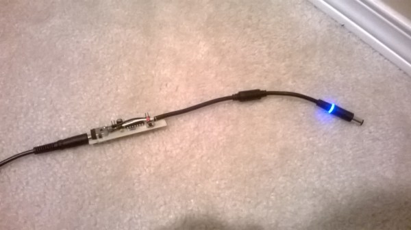
[Xuan] built a device that spoofs this identification information for Dell chargers. In the four-part series (1, 2, 3, 4), the details of reverse engineering the communications and building the spoofer are covered.

Dell uses the 1-Wire protocol to communicate with the charger, and [Xuan] sniffed the communication using a MSP430. After reading the data and verifying the CRC, it could be examined to find the fields that specify power, voltage, and current.

Next, a custom PCB was made with two Dell DC jacks and an MSP430. This passes power through the board, but uses the MSP430 to send fake data to the computer. The demo shows off a 90 W adapter pretending to run at 65 W. With this working, you could power the laptop from any supply that can meet the requirements for current and voltage.

Apple MagSafe Protocol Hacking

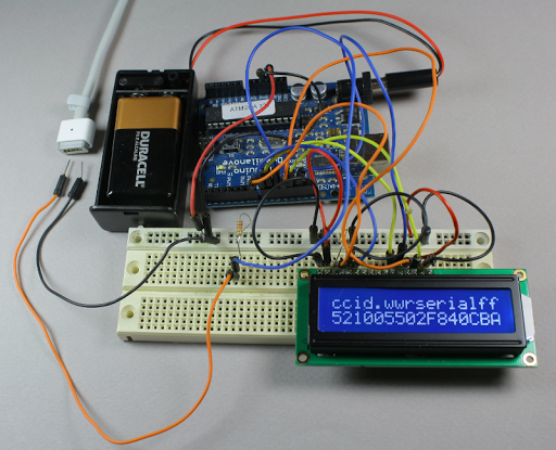
[Ken Shirriff] was interested in how the Apple MagSafe works. Specifically he wanted to know what controlled the LED on the connector itself so he tore one open to see what is inside. There’s a chip present and he didn’t waste time figuring out how the MagSafe communication protocol works.

The DS2413 chip he found on the MagSafe’s tiny little PCB has just six pins. Two of these control a pair of LEDs, which give the indicator its color range.  Another pin is used for 1-wire communications. When polled the charger will return a 64-bit identification number that includes a variety of information. [Ken] looks into what data is offered from several different models of charger by using the Arduino setup above. But the results are not entirely straight-forward as he discusses in his article. The 1-wire protocol is also used to switch the LEDs. This process is the responsibility of the computer being charged, but [Ken] shows how the colors can be cycled using an Arduino (with a couple of 9-volts as a source instead of a connection to mains).

Wireless 4 Channel Temperature Monitor From Arduino Libraries

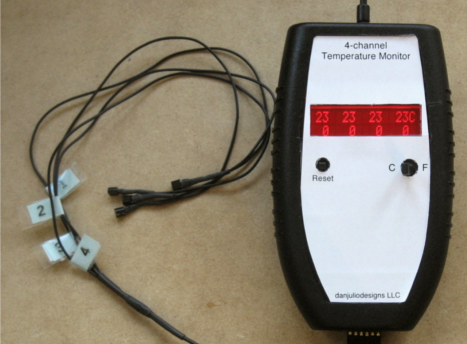
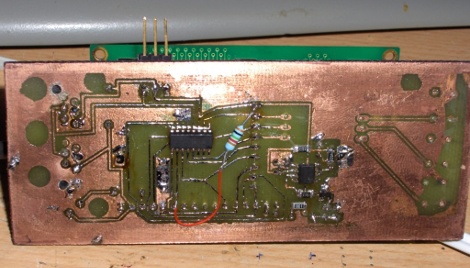
Say what you will about the Arduino platform but there certainly are a ton of libraries one can choose from. That is precisely what [Dan Julio] set out to do when building his slick looking 4 channel temperature monitor. The monitor consists of an Arduino RBBB, 2×16 character LCD and four DS18B20 1-wire digital thermometers. [Dan] also includes a bluesmirf to interface with an OS X monitoring program.  Using libraries for the Bluetooth, LCD, and temperature monitors the Arduino code is only about 200 lines, and pretty easy to follow. Check out more at [Dan]’s site.

If you’d like more temperature sensor projects check out this mug or this PIC based monitor or perhaps you’d like to keep it in the Atmel family.

1-Wire LAN With An LCD

[Viktor], one of our favorite avid hackers, has been playing around with 1-wire systems all this month. What started out as a MicroLAN Fonera has turned into an iButton interface, to a 1-wire powered hub, and finally a 1-wire character driven LCD. Anyone looking at 1-wire systems or OWFS could surely benefit from his testing.

However, if you still haven’t gotten your fill of 1-wire goodness, let us remind you of the 1-wire HVAC and IPv6 to 1-wire protocol translator.

[Thanks Juan]

Temperature And Electricity Monitoring

[Willem] has been using an Arduino to monitor temperatures and electricity usage. For the temperature monitoring he picked up some 1-wire temperature sensors similar to those we’ve featured in the past. To pick up on electricity usage he’s not using an amp sensors, but because he’s in the UK he does have a flashing LED on his power meter. There’s a known trick to pick up these flashes with a photo cell to calculate energy usage based on meter readings. Finally, the data from the three sensors (indoor temp, outdoor temp, and energy usage) is piped over the Internet via an Ethernet shield so that it can be collected and graphed.

[Willem] has had the system running for a year. If you’re nosy you can look at the temperature graph generated from his collected data.

1wire Attic Cooling

blower

[RagingComputer] built this 1-wire attic cooling fan. He’s using an Ubuntu server loaded with OWFS to control everything. The 1-wire temperature sensor is interfaced using USB while a serial x10 module sends out commands to be received by another x10 module near the fan. Back in the day we had covered a linux home automation project. We also covered HVAC hacks such as the smart attic fan and a 1-Wire HVAC monitoring system.

Parts: Unboxing The Bus Pirate

bp-unbox-3

For months we’ve used our Bus Pirate universal serial interface tool to demonstrate electronics parts, so it’s only appropriate that the Bus Pirate get it’s own parts post. We recently had a Bus Pirate preorder, and today we received the pre-production Bus Pirate prototype from Seeed Studio. This prototype was mailed just a few days before preorder 1 started to ship, so those packages should start arriving any day.

Follow along as we unbox the prototype Bus Pirate, and connect it to a debugger to determine the PIC24FJ64GA002-I/SO revision that shipped with this board. Use this post to share your own Bus Pirate unboxing experience. Pictures and discussion after the break.

Continue reading “Parts: Unboxing The Bus Pirate”