Building A Quadcopter With A CNC Mill And A 3D Printer

Quadcopter

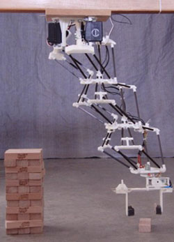
Quadcopters are a ton of fun to play with, and even more fun to build. [Vegard] wrote in to tell us about his amazing custom DIY quadcopter frame that uses a commercial flight control system.

Building a quadcopter is the perfect project to embark upon if you want to test out your new CNC mill and 3D printer. The mechanical systems are fairly simple, yet result in something unbelievably rewarding. With a total build time of 30 hours (including Sketchup modeling), the project is very manageable for weekend hackers. [Vegard’s] post includes his build log as well as some hard learned lessons. There are also tons of pictures of the build. Be sure to read to read the end of the post, [Vegard] discusses why to “never trust a quadcopter” and other very useful information. See it in action after the break.

While the project was a great success, it sadly only had about 25 hours of flight-time before a fatal bird-strike resulted in quite a bit of damage. Have any of your quadcopters had a tragic run-in with another flying object? Let us know in the comments.

Continue reading “Building A Quadcopter With A CNC Mill And A 3D Printer”

Dispensing Solder Paste With A 3D Printer

There’s a strange middle ground in PCB production when it comes to making a few boards. Dispensing solder paste onto one board is easy enough with a syringe or toothpick, but when pasting up even a handful of boards, this method gets tiresome. Solder paste stencils speed up the process when you’re doing dozens or hundreds of boards, but making a stencil for just a few boards is a waste. The solution for this strange middle ground is, of course, to retrofit a 3D printer to dispense solder paste.

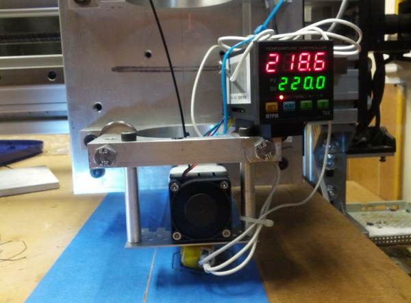
This project was a collaboration between [Jake] and [hzeller] to transform KiCAD files to G Code for dispensing solder paste directly onto a board. The machine they used was a Type A Machines printer with a solder paste dispenser in place of an extruder. The dispenser is hooked up to the fan output of the controller board, and from the looks of the video, they’re getting pretty good results for something that’s still very experimental.

All the code to turn KiCAD files into G Code are up on [hzeller]’s github. If you’re wondering, the board they’re pasting up is a stepper driver board for the BeagleBone named Bumps.

Videos below.

Continue reading “Dispensing Solder Paste With A 3D Printer”

Ask Hackaday: Auto Bed Leveling And High Temperature Force Sensitive Resistors

FSR

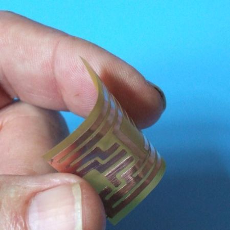
[Johann] over on the RepRap wiki has an ingenious solution for making sure a borosilicate glass bed is completely level before printing anything on his Kossel printer: take three force sensitive resistors, put them under the build platform, and wire them in parallel, and connect them to a thermistor input on an electronics board. The calibration is simply a bit of code in the Marlin firmware that touches the nozzle to the bed until the thermistor input maxes out. When it does, the firmware knows the print head has zeroed out and can calculate the precise position and tilt of the bed.

Great, huh? A solution to bed leveling that doesn’t require a Z-probe, uses minimal (and cheap) hardware, and can be retrofitted into just about any existing printer. There’s a problem, though: these force sensitive resistors are only good to 70° C, making the whole setup unusable for anything with a heated bed. Your challenge: figure out a way to use this trick with a heated bed.

The force sensitive resistors used – here’s a link provided by [Johann] – have a maximum operating temperature of 70° C, while the bed temperature when printing with ABS is around 130° C. The FSRs are sensitive to temperature, as well, making this a very interesting problem.

Anyone with any ideas is welcome to comment here, on the RepRap forums, the IRC, or anywhere else. One idea includes putting an FSR in the x carriage, but we’re thinking some sort of specialized heat sink underneath the bed and on top of the FSRs would be a better solution.

Video of the auto bed leveling trick in action below.

Continue reading “Ask Hackaday: Auto Bed Leveling And High Temperature Force Sensitive Resistors”

4 Axis Delta Router Says Hello World

deltaRouter

[Bart] stood upon the shoulders of the delta 3D printer giants and created this 4 axis delta router. The router was originally created for ORD Camp, an invite only hackers gathering. Each year he creates a new thing with one main purpose: to spark conversation. In his own words “Practicality and suitability are way down the list, so go ahead and snark away. If you do, you are missing the point.”

[Bart] did things a bit differently with his delta. For motors, he went with non captive steppers. “Non captive” means that rather than a shaft, the motor has a hollow threaded nut which rotates. A lead screw (usually with an acme thread) is passed through this nut. As the motor’s nut turns, the screw is pushed or pulled through the motor, creating a linear actuator. The only major downside is that a non captive stepper motor can’t be adjusted by hand. The screw doesn’t turn and neither do any external parts of the motor. For structure, the router uses MakerSlide and v-grove wheels. The spindle is a simple brushless hobby motor and 30 amp speed control. Rather than the outrunner motors we’ve seen lately, [Bart] wisely chose an inrunner motor normally used on R/C cars. Inrunners generally have less torque than their outrunner counterparts, but they make up for this in RPM. [Bart’s] motor is capable of 30,000 RPM, which is plenty for spindle duty. We think the motor bearings will probably need an upgrade, as the original motor bearings weren’t designed for side loads. For a controller, [Bart] utilized an  Azteeg X3 running Repetier.

The router made a great showing at camp, and [Bart] decided it needed a 4th axis. He sourced a rotary axis from eBay. To keep the software simple, he connected the rotary axis to the extruder outputs on his controller. He was then able to hack the mach3 wrapped rotary post processor to output extruder commands. The results look great. [Bart] says the system definitely needs a tailstock, and we agree. We’re looking forward to the next update on this machine!

Continue reading “4 Axis Delta Router Says Hello World”

Ask Hackaday: What’s Up With This Carbon Fiber Printer?

The Hackaday Tip Line has been ringing with submissions about the Mark Forg3D printer, purportedly the, “world’s first 3D printer that can print carbon fiber.”

Right off the bat, we’re going to call that claim a baldfaced lie. Here’s a Kickstarter from a few months ago that put carbon fiber in PLA filament, making every desktop 3D printer one that can print in carbon fiber.

But perhaps there’s something more here. The Mark Forged site gives little in the way of technical details, but from what we can gather from their promo video, here’s what we have: it’s a very impressive-looking aluminum chassis with a build area of 12″x6.25″x6.25″. There are dual extruders, with (I think) one dedicated to PLA and Nylon, and another to the carbon and fiberglass filaments. Layer height is 0.1mm for the PLA and Nylon, 0.2mm for the composites. Connectivity is through Wifi, USB, or an SD card, with a “cloud based” control interface. Here are the full specs, but you’re not going to get much more than the previous few sentences.

Oh, wait, it’s going to be priced at around $5000, which is, “affordable enough for average consumers to afford.” Try to contain your laughter as you click the ‘read more’ link.

Continue reading “Ask Hackaday: What’s Up With This Carbon Fiber Printer?”

A Quick And Simple Filament Joiner For Multi-Color Prints

Filament splicer

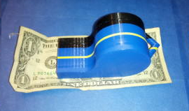
[Malcolm] was having a grand time with his new 3D printer. He was getting tired of monochromatic prints, though. Not having a machine with multiple extruders, he went looking for a way to join pieces of filament. There were a few designs on Thingiverse, but they required milled parts that he didn’t have the tools to recreate. Rather than invest in a mill, [Malcolm] decided to build his own filament joiner. He started by raiding his wife’s hair care tools. His first test was a curling iron. It had the heat, but lacked a good surface to join the filament. [Malcolm’s] next test was a ceramic hair straightener, which he found to be the perfect tool.

The splicing process is simple. Start with a hot iron, then lay two pieces of filament on top of the short end of the iron. They soften quickly and melt together. [Malcolm’s] real trick is to slightly pull the joint once the two pieces have joined. Pulling causes the filament to stretch, slightly reducing the diameter of the joint. A thinner joint helps prevent extruder jams as the joint passes through. This method works great for PLA. We’d love to see if it works for ABS as well.

Click past the break for an example piece and for [Malcom’s] instructional video.

Continue reading “A Quick And Simple Filament Joiner For Multi-Color Prints”

3DMonstr Printer: 8 Cubic Feet Of Build Volume

3D Monster

So you’re looking at 3D printers, but the build volumes for the current offerings just aren’t where you’d like them to be. [Ben Reylblat] had the same problem and came up with the 3DMonstr, an enormous printer that has (in its biggest configuration) a two foot cubed build volume, four extruders, and the mechanical design to make everything work.

Most of the ginormous 3D printers we’ve seen are basically upgraded versions of the common table-top sided models. This huge Ultimaker copy uses the same rods as its smaller cousin, and LeBigRap also uses woefully undersized parts. The 3DMonstr isn’t a copy of smaller machines, and instead uses very big motors for each axis, ball screws, and a proper welded frame. It’s highly doubtful anyone will call this printer a wobblebot.

The 3DMonstr comes in three sizes: 12 inches cubed, 18 inches cubed, and 24 inches cubed, with options for two to four extruders.  We caught up with the 3D Monstr team at the NYC Maker Faire, and from first impressions we have to say this printer is freakin’ huge and impeccably designed.