Better 3D-Printed Bridges Are Possible, With The Right Settings

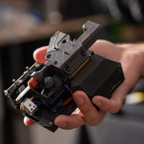
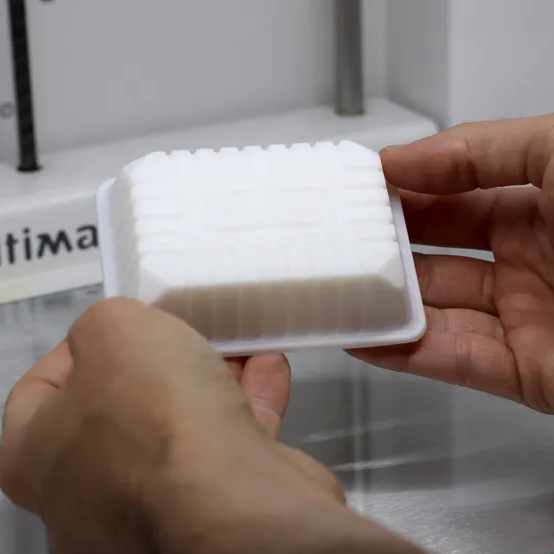
The header image above shows a completely unsupported 3D-printed bridge, believe it or not. You’re looking at the bottom of the print. [Make Wonderful Things] wondered whether unsightly unsupported bridges could be improved, and has been busy nailing down remarkably high-quality results by exhaustive testing of different settings.

It all started when they thought that unsupported bridges looked a lot as though they were made from ropes stretched between two points. Unlike normal layers, these stretched extrusions didn’t adhere to their neighbors. They are too far apart from one another, and there’s no “squish” to them. But could this be overcome?

His experiments centered mainly around bridge printing speed, temperature, and bridge flow. That last setting affects how much the extrusion from the hot end is adjusted when printing a bridge. He accidentally increased it past 1.0 and thought the results were interesting enough to follow up on; it seemed that a higher flow rate when printing a bridge gave the nudge that was needed to get better inter-line adhesion. What followed was a lot of testing, finally settling on something that provided markedly better results than the stock slicer settings. Markedly better on his test pieces, anyway.

BF = Bridge flow, BS = Bridge printing speed (in mm/sec)

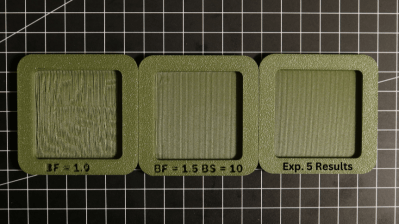
The best results seem to come from tweaking the Bridge Flow rate high enough that extrusions attach to their neighbors, printing slowly (he used 10 mm/sec), and ensuring the bridged area is as consistent as possible. There are still open questions, like some residual sagging at corners he hasn’t been able to eliminate, but the results otherwise look great. And it doesn’t even require laying one’s printer on its side!

All the latest is on the project page where you can download his test models, so if you’re of a mind to give it a try be sure to check it out and share your results. Watch a short video demonstrating everything, embedded just under the page break.

Thanks to [Hari] for the tip!

Continue reading “Better 3D-Printed Bridges Are Possible, With The Right Settings”

3D Printering: Liquid-Filled Filament Was Not On Our Bingo Card

[Prusa] have a number of announcements, and one of the more unusual ones is that liquid printing is coming to the Prusa XL. Specifically, printing in real, heat-resistant silicone (not a silicone-like plastic) is made possible thanks to special filament and a special toolhead. It’s the result of a partnership with Filament2, and the same process could even be used to print with other liquids, including chocolate.

Look closely and you will see the detail in the nozzle, which mixes the two-part formula.

The process is as unusual as it is clever. The silicone is a two-part formula, but there is no reservoir or pump involved. Instead, there are two filaments, A and B. When mixed, they cure into solid silicone.

What is unusual is that these filaments have a liquid core. Upon entering the extruder, the outer sheath is cut away, and the inner liquid feeds into a mini mixing nozzle. The nozzle deposits the mixed silicone onto the print, where it cures. It isn’t clear from the demo where the stripped outer casing goes, but we assume it must get discarded or is possibly stowed temporarily until it can be removed.

Liquid-core filament is something we certainly didn’t have on our bingo card, but we can see how it makes sense. A filament format means the material can be handled, fed, and deposited precisely, benefiting from all of the usual things a filament-based printer is good at doing.

What’s also interesting is that the liquid toolhead can co-exist with other toolheads on the XL; in fact, they make a point of being able to extrude silicone as well as the usual thermoplastics into the same print. That’s certainly a trick no one else has been able to pull off.

There are a few other announcements as well, including a larger version of their Core One printer and an open-source smart spool standard called OpenPrintTag, a reusable and reprogrammable NFC insert for filament spools that gives you all of the convenience of automating color and material reading without the subtle (or overt) vendor lock-in that comes with it.

Watch a demo of the new silicone extruder in the video, embedded just under the page break. The new toolhead will be 1,009 USD when it launches in early 2026.

Continue reading “3D Printering: Liquid-Filled Filament Was Not On Our Bingo Card”

What’s New In 3D Scanning? All-In-One Scanning Is Nice

3D scanning is important because the ability to digitize awkward or troublesome shapes from the real world can really hit the spot. One can reconstruct objects by drawing them up in CAD, but when there isn’t a right angle or a flat plane in sight, calipers and an eyeball just doesn’t cut it.

Scanning an object can create a digital copy, aid in reverse engineering, or help ensure a custom fit to something. The catch is making sure that scanning fits one’s needs, and isn’t more work than it’s worth.

I’ve previously written about what to expect from 3D scanning and how to work with it. Some things have changed and others have not, but 3D scanning’s possibilities remain only as good as the quality and ease of the scans themselves. Let’s see what’s new in this area.

All-in-One Handheld Scanning

MIRACO all-in-one 3D scanner by Revopoint uses a quad-camera IR structured light sensor to create 1:1 scale scans.

3D scanner manufacturer Revopoint offered to provide me with a test unit of a relatively new scanner, which I accepted since it offered a good way to see what has changed in this area.

The MIRACO is a self-contained handheld 3D scanner that, unlike most other hobby and prosumer options, has no need to be tethered to a computer. The computer is essentially embedded with the scanner as a single unit with a touchscreen. Scans can be previewed and processed right on the device.

Being completely un-tethered is useful in more ways than one. Most tethered scanners require bringing the object to the scanner, but a completely self-contained unit like the MIRACO makes it easier to bring the scanner to the subject. Scanning becomes more convenient and flexible, and because it processes scans on-board, one can review and adjust or re-scan right on the spot. This is more than just convenience. Taking good 3D scans is a skill, and rapid feedback makes practice and experimentation more accessible.

Continue reading “What’s New In 3D Scanning? All-In-One Scanning Is Nice”

Art of 3D printer in the middle of printing a Hackaday Jolly Wrencher logo

3D Printering: Speed Is So Hot Right Now

Speed in 3D printing hasn’t been super important to everyone. Certainly, users value speed. But some value quality even more highly, and if gaining quality means giving up speed, then so be it. That’s more or less how things stood for a while, but all things change.

The landscape of filament-based 3D printing over the past year or so has made one thing clear: the market’s gotten a taste of speed, and what was once the domain of enthusiasts installing and configuring custom firmware is now a baseline people will increasingly expect. After all, who doesn’t want faster prints if one doesn’t have to sacrifice quality in the process?

Speed vs. Quality: No Longer a Tradeoff

Historically, any meaningful increase in printing speed risked compromising quality. Increasing print speed can introduce artifacts like ringing or ghosting, as well as other issues. Printing faster can also highlight mechanical limitations or shortcomings that may not have been a problem at lower speeds. These issues can’t all be resolved by tightening some screws or following a calibration process.

The usual way to get into higher speed printing has been to install something like Klipper, and put the necessary work into configuring and calibrating for best results. Not everyone who prints wishes to go this route. In 3D printing there are always those more interested in the end result than in pushing the limits of the machine itself. For those folks, the benefits of speedy printing have generally come at too high a cost.

That’s no longer the case. One can now buy a printer that effectively self-calibrates, offers noticeably increased printing speeds over any earlier style machines, and does it at a reasonable price.

Continue reading “3D Printering: Speed Is So Hot Right Now”

Art of 3D printer in the middle of printing a Hackaday Jolly Wrencher logo

G-code Goes Binary With Proposed New Format

G-code is effective, easily edited, and nearly ubiquitous when it comes to anything CNC. The format has many strengths, but space efficiency isn’t one of them. In fact, when it comes to 3D printing in particular file sizes can get awfully large. Partly to address this, Prusa have proposed a new .bgcode binary G-code format. You can read the specification of the new (and optional) format here.

The newest version of PrusaSlicer has support for .bgcode, and a utility to convert ASCII G-code to binary (and back) is in the File menu. Want to code an interface of your own? The libbgcode repository provides everything needed to flip .gcode to .bgcode (with a huge file size savings in the process) and vice versa in a way that preserves all aspects of the data. Need to hand-edit a binary G-code file? Convert it to ASCII G-code, make your changes, then flip it right back.

Prusa are not the only ones to notice that the space inefficiency of the G-code file format is not ideal in all situations. Heatshrink and MeatPack are two other solutions in this space with their own strong points. Handily, the command-line tool in libgcode can optionally apply Heatshrink compression or MeatPack encoding in the conversion process.

In a way, G-code is the assembly language of 3D printers. G-code files are normally created when slicing software processes a 3D model, but there are some interesting tricks to be done when G-code is created directly.

Art of 3D printer in the middle of printing a Hackaday Jolly Wrencher logo

Make Better 3D Printed Molds, For Thermoforming Plastics

Thermoforming — which includes vacuum-forming — has its place in a well-rounded workshop, and Mayku (makers of desktop thermoforming machines) have a short list of tips for getting the best results when 3D printing molds on filament-based printers.

A mold is put into direct, prolonged contact with a hot sheet of semi-molten plastic. If one needs a mold to work more than once, there are a few considerations to take into account. The good news is that a few simple guidelines will help get excellent results. Here are the biggest ones:

  1. The smoother the vertical surfaces, the better. Since thermoforming sucks (or pushes) plastic onto and into a mold like a second skin, keeping layer heights between 0.1 mm and 0.2 mm will make de-molding considerably easier.
  2. Generous draft angles. Aim for a 5 degree draft angle. Draft angles of 1-2 degrees are common in injection molding, but a more aggressive one is appropriate due to layer lines giving FDM prints an inherently non-smooth surface.
  3. Thick perimeters and top layers for added strength. The outside of a mold is in contact with the most heat for the longest time. Mayku suggests walls and top layer between 3 mm to 5 mm thick. Don’t forget vent holes!
  4. Use a high infill to better resist stress. Molds need to stand up to mechanical stress as well as heat. Aim for a 50% or higher infill to make a robust part that helps resist deformation.
  5. Ensure your printer can do the job. 3D printing big pieces with high infill can sometimes lift or warp during printing. Use enclosures or draft shields as needed, depending on your printer and material.
  6. Make the mold out of the right material. Mayku recommends that production molds be printed in nylon, which stands up best to the heat and stress a thermoforming mold will be put under. That being said, other materials will work for prototyping. In my experience, even a PLA mold (which deforms readily under thermoforming heat) is good for at least one molding.

Thermoforming open doors for an enterprising hacker, and 3D printing molds is a great complement. If you’re happy being limited to small parts, small “dental” formers like the one pictured here are available from every discount overseas retailer.  And of course, thermoforming is great for costumes and props. If you want to get more unusual with your application, how about forming your very own custom-shaped mirrors by thermoforming laminated polystyrene?

Art of 3D printer in the middle of printing a Hackaday Jolly Wrencher logo

PrusaSlicer Now Imports STEP Files, Here’s Why That’s A Big Deal

PrusaSlicer has a new feature: the ability to import a CAD model for 3D printing. Starting in version 2.5.0-beta1, PrusaSlicer can import STEP format 3D models. An imported STEP file is converted to a triangle mesh on import (making it much like a typical .stl or .3mf file) which means that slicing all happens as one would normally expect. This is pretty exciting news, because one is not normally able to drop a CAD format 3D model directly into a slicer. With this change, one can now drag .stp or .step files directly into PrusaSlicer for printing.

First, a brief recap. In the world of 3D models there are two basic kinds: meshes and CAD models. The two work very differently, especially when it comes to editing. 3D printing has a long history of using .stl files (which are meshes) but making engineering-type changes to such files is difficult. Altering the size of a thread or changing mounting holes in a CAD model is easy. On an STL, it is not. This leads to awkward workarounds when engineering-type changes are needed on STLs. STEP, on the other hand, is a format widely supported by CAD programs, and can now be understood by PrusaSlicer directly. Continue reading “PrusaSlicer Now Imports STEP Files, Here’s Why That’s A Big Deal”