Discrete Logic Driving Game Development

[Caleb] is hard at work on a driving game based on 7400 series logic chips. This will be his entry in the Open 7400 Logic Competition, and it really outlines why this contest is especially tricky.

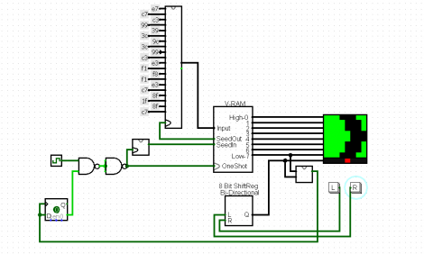
The concept behind the game is quite simple. You’re the driver of a car (the red dot at the bottom of the display square seen above) and need to navigate the curves in the road as you drive along. It’s the same game as we saw played on receipt paper back in June. [Caleb’s] using and LED matrix as the display, and we’re confident that if we grabbed our favorite microcontroller we could have this up and running on an 8×8 bi-color display in an afternoon. But doing it without the crutch of a programmable chip really brings out the clever engineer inside of you.

The circuit seen above is a Logisim proof-of-concept that [Caleb] went on to test on the breadboard. He thought he had everything figured out until he realized that his Data Flip-Flops were very occasionally not powering up in the same state as he predicted. Don’t worry, he found a solution to the problem. But we can’t wait to see what other hurdles he encounters as he pushes on toward completing the project.

Get Out The Graph Paper Get Started On The New Discrete Logic Contest

Here’s another chance to ply your hacking skills for cash and prizes. Dangerous Prototypes has just announced the Open 7400 Logic Competition. First prize is $100 and a bunch of hacking goodies. But even better is that since it was announced, more sponsors have stepped up to increase the kitty, and the number of entries that will get prizes.

The parameters for entry are wide open. You can design anything you want, with emphasis on originality. Make sure you take plenty of pictures and document the project along the way. Their judging will take into consideration the amount of detail posted about the project (hence the ‘Open’ in the contest title).

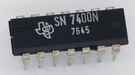
Need some ideas to get you started? We enjoyed the useless machine that used a 7400 NAND gate. You could always build a time piece of some sort like this no-microcontroller clock. Perhaps hardware control like this stepper motor driver is more to your liking?

[Thanks Moderboy]

Most Useless Machine Upgrade — Now With A Button!

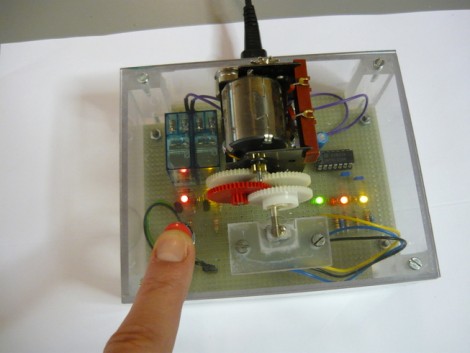
There’s a soft spot in our hearts for pointless projects, as long as they’re well executed. [Bertho] really hit the mark with his take on the most useless machine. We’ve seen several renditions of this concept, most of them hinging on a box that will turn a mechanical switch off whenever you turn it on. But this take uses a push button to activate a switch flipping mechanism on another part of the machine.

You can see the drive gears in the image above. The final gear has a small bar which flips a switch to one side or the other. The circuit does this without the need of a microcontroller. A 7400 series NAND gate chip, some passive components, and two mechanical relays are all it takes. At each push of the button, the logic chip trips one of the relays to trigger the appropriate motor direction based on the current state of that switch. You can press the button during movement, but all that will do is delay the inevitable flip of the switch.

Larson Scanner Using 7400 Series Logic Hardware

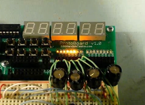
[RandomTask] is sharing a Larson scanner he built a few decades ago. These days you can whip one of these up using an Arduino in under an hour. He mentions this, but we agree that for nostalgic purposes there’s nothing like implementing the scanning LED effect using hardware.

Often called a Cylon Eye (after the television show Battlestar Gallactica) or referred to as the lights on the front of Kitt (the car from Knight Rider), the effect doesn’t just involve switching LEDs on and off in the proper order. A true Larson Scanner fades the LEDs as the bright point moves away from them, resulting in a tail that dims over time.

This implementation uses a 555 timer as the clock signal, allowing for speed control through a potentiometer. A counter chip, J-K flipflop, and line decoder all work with each other to address the movement of the brightest light. The fading effect is managed via a capacitor and resistor for each LED. The video after the break shows the pleasing result of this setup.

Continue reading “Larson Scanner Using 7400 Series Logic Hardware”

Pure TTL Based Clock

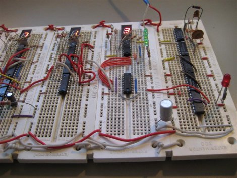
We’ll just say, [Kenneth] really likes clocks. His most recent is a pure 7400 series TTL based one, ie no microcontroller as seen in the past, here, here, and here. The signal starts out as a typical 32,768 crystal divided down to the necessary 1Hz, which is then divided again appropriately to provide hours and minutes.

As far as TTL clocks go, this is nothing too original; until it comes to his creative button interface. By using a not as sexy as it sounds multivibrator, he can produce a clean square wave instead of the figity signals produced from buttons to advance and set the time. Like always, he also provides us with a thorough breakdown of his clock, after the jump. Continue reading “Pure TTL Based Clock”

Working With VFDs

vfd

We love old display technology, like Nixie tubes, but they’re often difficult to work with because they require higher voltages than digital logic. Vacuum florescent displays (VFD) fall into this category. While not necessarily “old”, they are becoming far less common than LCDs. The main benefit of a VFD is that it actually produces light directly; it doesn’t require a backlight. You’ll find these displays on various players and appliances: CD, DVD, VCR, microwaves, stoves, car headunits, and others.

[Sprite_tm] had written off some VFDs, but recently revisited them with renewed interest. He started by testing what sort of voltage would be required to drive the display. It took 3V for the filament plus 15V to drive the grids. There are VFD controller chips available, but he wanted to get this working with what he had on hand. He had experience with older 40xx series logic, which can be powered by much higher voltages than 5V 74xx. His final schematic has three 4094 serial to parallel chips with an ATtiny2313 controller. A 5V power supply is dropped to 3V with diodes to drive the filament while a boost converter brings it up to 15V for the 4094s that switch the segments. While the code is specific to this display, it would be a great place to start your own project.