EL Wire: Make It, Connect It, Power It

[Jeri’s] back with a series of videos that outlines the step-by-step electroluminescent wire manufacturing, making EL panels from PCBs, and assembling power supplies for EL hardware. These concepts are actually quite approachable, something we don’t expect from someone who makes their own integrated circuits at home.

The concept here is that an alternating current traveling through phosphors will excite them and produce light. You need two conductors separated by a dielectric to get the job done. For wire, [Jeri] uses one strand of enameled magnet wire and one strand of bare wire. The enamel insulates them, protecting against a short circuit.

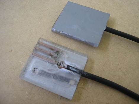
But that’s not all, she also tests using a circuit board as an EL panel. By repurposing the ground plane as one of the conductors, and using the solder mask as the dielectric she is able to paint on a phosphor product resulting in the glowing panel.

Finally, you’ve got to get juice to the circuit and that’s where her power supply video comes into the picture. We’ve embedded all three after the break. It’s possible that this is cooler than blinking LEDs and it’s fairly inexpensive to get started. The circuitry is forgiving, as long as you don’t zap yourself with that alternating current.

Continue reading “EL Wire: Make It, Connect It, Power It”

Super Simple Arduino Setup Lowers Electricity Bills

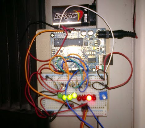
An Arduino with 40 lines of code, a temperature resistor, and servo are all that’s truly needed to save some dough with this thermostat by [Peter Hamilton]. LEDs and a potentiometer are added as well to help set and read the desired temperature. With or without said additional parts, the hack is still ridiculously simple and we’re wondering why we didn’t have a similar setup on our blisteringly cold office AC system before seeing it.

Though, we’re going a bit further with our version, plans are in the making to add timers to turn off the system for extended hours while no one is at the office. What would you add?

Neon Binary Clock

[Josiah] said ‘no’ to LEDs and instead used blue-phosphor neon lamps to build this binary clock. The ATmega328 inside uses three 8-bit shift registers to control the display. Each lamp needs a high-voltage NPN transistor in order to switch on the 150V necessary for proper illumination. A simple circuit was used to pull a 60 Hz clock signal out of the incoming 16VAC power. Unfortunately it was a bit too simple and didn’t provide a clean signal. [Josiah’s] workaround is something of a debounce subroutine in the firmware to prevent multiple interrupts on the falling edge.

The last project we saw from [Josiah] was the Coachella Lamp. That was a show piece of antiquated technology and this is another show piece with a minimalistic style. We also liked seeing the protoboard work on the inside. That’s a pretty jam-packed circuit board and keeping everything in the right place while you build up each trace with blobs of solder is no small feat.

SPRIME Controlled AC Outlets

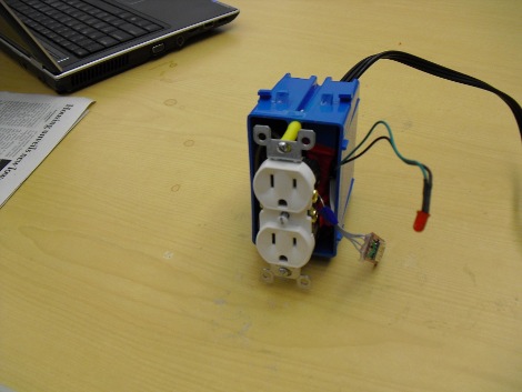
Reader [Tim Upthegrove] sent in a novel take on powering and monitoring AC outlets and devices called SPRIME, or Simple Powerline Remote Interactive Monitor and Enforcer. Compared to previous hacks, such as 120v switching or Quick cheap remote outlets, that only turned an outlet on or off; SPRIME allows not only control over outlets via the internet, but also power usage of devices currently plugged in.

We really liked their idea of giving power companies access to SPRIME outlets to reduce power consumption during peak hours, but sadly we don’t see it being implemented in homes any time soon. Catch a video of SPRIME after the rift.

[Thanks Chris McClanahan and Jeff Starker for the project, and deyjavont for pointing out our silly mistakes]

Continue reading “SPRIME Controlled AC Outlets”

Logic Clock Without An On-board Oscillator

[Lucassiglo21] developed this logic clock without using a crystal oscillator or a resonator. Instead, he’s letting the incoming electricity keep the time for him. The supply is AC at 50 Hz so he’s using some 4017 decade dividers to reduce that down to a 1 Hz signal. From there it keeps track of the ticks just like the last digital logic clock we saw.

If you’ve used AC line frequency as the clock source in your project we’d like to hear about it. Send us a tip and make sure your writeup includes a schematic. We’re especially interested to see if anyone has a good way of using this method with inexpensive microcontrollers.

Robot Waits For No Man When Recharging

Yikes, that power connector certainly wasn’t designed by Apple. Ugly as it may be, it’s the charging cable for a robot and acts as a sensor that allows the robot to properly align and plug into a power receptacle.

We’re going to go off on a tangent for just a second. We often think of the Rat Things from Snowcrash when considering robot power. They were nuclear powered (or something) and instead of recharging required constant cooling. Those day’s aren’t exactly around the corner but we think they’ve been realized in the lawn mowing robots that have a little nests to recharge in. Base stations work but they require the machine to return to the same place, or to have multiple charging stations.

The point is, this specialized cable makes base stations for robots obsolete. Now a robot can plug into any outlet it can get near, a great thing for robots roving large facilities. After the break you can see a video of this process. The robot arm zeros in by scanning horizontally and vertically and measuring the magnetic field put out by the AC in the wires of the outlet. Take a look, it’s a pretty neat piece of engineering.

Continue reading “Robot Waits For No Man When Recharging”

Arduino Traffic Light

[Rockwell] sent us an update on his traffic light hacking. Dedicated readers will remember seeing this legally attained traffic signal controlled through a parallel port from back in 2005. The new update swaps the old port for USB and adds several autonomous functions which are demonstrated in the clip after the break. The update includes a nice UI and some notifications for things like email, IMs, Reddit posts, etc.

He’s given control of the hardware over to an Arduino. Instead of building the board into the project he’s included just the parts he needs; an AVR running the Arduino bootloader, a crystal and filtering caps, and an Arduino serial to USB module for connectivity. The AC load switching is handled by three relays. The relays he links to are 12VCD rated coils. We think this should have pointed to 5VDC coils as that’s the voltage that the logic circuit are running at. Be careful with switching these AC loads, this traffic light isn’t a toy.

Continue reading “Arduino Traffic Light”