Light Bulb, Diode, And Capacitor Step Mains Down To 12V DC

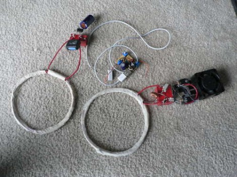
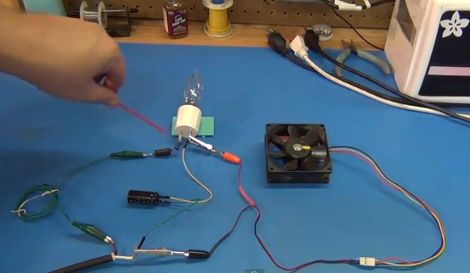
[Todd Harrison] needed a way to run a 12 volt PC fan from mains voltage. Well, we think he really just needed something to keep him occupied on a Sunday, but that’s beside the point. He shows us how he did this in a non-traditional way by using the resistive load of an incandescent light bulb, a diode, and a capacitor to convert voltage to what he needed. You can read his article, or settle in for the thirty-five minute video after the break where he explains his circuit.

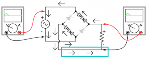
The concept here is fairly simple. The diode acts as a half-wave rectifier by preventing the negative trough of the alternating current from passing into his circuit. The positive peaks of the electricity travel through the light bulb, which knocks down the voltage to a usable level. Finally, the capacitor fills the gaps where the negative current of the AC used to be, providing direct current to the fan. It’s easy to follow but the we needed some help with the math for calculating the correct lightbulb to use to get our desired output current.

Continue reading “Light Bulb, Diode, And Capacitor Step Mains Down To 12V DC”

High Voltage: How To Cook Your Goose In 62 Easy Steps

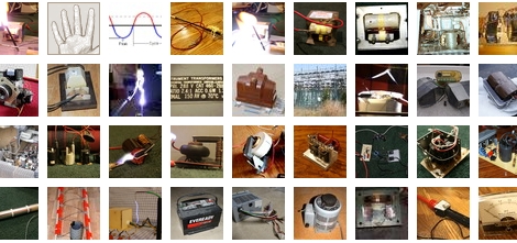
Prepare to learn. [Grenadier] has put together a collection of information about AC electricity that can safely be called a super-post. In 62 parts he covers a myriad of topics, some of them safe, many of them not so much. You may want to spend time reading through everything that he has to offer, but just in case you don’t, step one is a table of contents. In it you’ll find a listing of major points including transformers of every kind imaginable; from microwave ovens, neon signs, bug zappers, x-rays, and televisions. [Grenadier] covers the type of transformers that these items use, where to find them, and how to set up your own experiments. There’s plenty of pictures and several videos where the high-powered sparks fly. We feel like there’s enough here that we can be satisfied with vicarious AC interactions while safely in front of our monitor and far away from the heart-stopping action.

[Thanks Marcus]

Power Adapter For Digital Cameras Without An External Jack

[Kusnick] is into using digital camera rigs for book scanning. The problem is that keeping the batteries charged is a pain, but there’s no external AC adapter jack which would allow him to use the mains. His solution was to build his own adapter to replace the batteries.

There are some fancy book scanning setups that allow you to just flip through the pages, but it’s much simpler to build a rig that uses two cameras. [Kusnick’s] setup is the latter, which means he’s found two inexpensive cameras that don’t need to be mobile. The first attempt at making an adapter featured a block of acrylic with the positive and negative contacts connected to a shielded cord which he then hooked to an external supply. The camera would come on and then turn off citing that the cameras were “for use with compatible battery only”. Turns out there’s some type of verification circuit built into the proprietary batteries. But the solution to that came quite easily; remove the circuit board from the battery and insert it in the adapter to trick the camera.

[Thanks Daniel]

Touch Sensors: Overview, Theory, And Construction

This collection of touch sensor information should be of interest to anyone who liked the simple touch sensor post from Thursday. That was a resistive touch sensor and is covered in detail along with AC hum sensors that trigger based on induced current from power lines around you, and capacitive touch switches like we’ve seen in past hacks. Each different concept is discussed and clearly illustrated like the slide above. [Giorgos Lazaridis] has also put together individual posts that build and demonstrate the circuits. We’ve embedded his resistive sensor demo video after the break and linked to all three example circuits.

Continue reading “Touch Sensors: Overview, Theory, And Construction”

Power Supplies And Transformers; A Learning Experience

[Ladyada] is working on a tutorial series covering power supplies. If you’ve ever built an electronic project you’ve used some type of power supply but we think that most people have no idea how you get from mains power to the DC voltages that most small projects use. So if you want to learn, get started with the first installment which covers AC/DC converters based on a transformer like the one seen above.

These transformers are inside the heavy and hot wall-wart plugs that come with many electronics. We used one along with a breadboard power supply when building the pumpkin LED matrix. They use a pair of coils to step down the voltage to a much smaller level. From there it’s a matter of rectifying the AC into DC power, which she talks about in an easy to follow discussion.

We understand this type of converter quite well but we’re a bit foggy on switch-mode AC/DC converters that don’t use a transformer. They’re much better because you don’t have to build a regulator into the target project like you do with wall-warts. Can’t wait until she gets to that part of the series!

EL Wire: Make It, Connect It, Power It

[Jeri’s] back with a series of videos that outlines the step-by-step electroluminescent wire manufacturing, making EL panels from PCBs, and assembling power supplies for EL hardware. These concepts are actually quite approachable, something we don’t expect from someone who makes their own integrated circuits at home.

The concept here is that an alternating current traveling through phosphors will excite them and produce light. You need two conductors separated by a dielectric to get the job done. For wire, [Jeri] uses one strand of enameled magnet wire and one strand of bare wire. The enamel insulates them, protecting against a short circuit.

But that’s not all, she also tests using a circuit board as an EL panel. By repurposing the ground plane as one of the conductors, and using the solder mask as the dielectric she is able to paint on a phosphor product resulting in the glowing panel.

Finally, you’ve got to get juice to the circuit and that’s where her power supply video comes into the picture. We’ve embedded all three after the break. It’s possible that this is cooler than blinking LEDs and it’s fairly inexpensive to get started. The circuitry is forgiving, as long as you don’t zap yourself with that alternating current.

Continue reading “EL Wire: Make It, Connect It, Power It”

Super Simple Arduino Setup Lowers Electricity Bills

An Arduino with 40 lines of code, a temperature resistor, and servo are all that’s truly needed to save some dough with this thermostat by [Peter Hamilton]. LEDs and a potentiometer are added as well to help set and read the desired temperature. With or without said additional parts, the hack is still ridiculously simple and we’re wondering why we didn’t have a similar setup on our blisteringly cold office AC system before seeing it.

Though, we’re going a bit further with our version, plans are in the making to add timers to turn off the system for extended hours while no one is at the office. What would you add?