The availability of cheap radios, omni-present WiFi and powerful web services means the IoT wave is here to stay. Amazon got into the act with its “do only one thing” Dash button. But a more interesting solution would be an IoT “do it all” button.
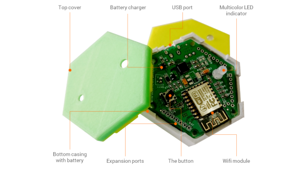
[Anand] has been working on his 1btn Open Source WiFi connected IoT button for a while. It connects to the Internet over WiFi to trigger whatever action you have assigned to it using a simple, online interface. It’s reconfigurable and open source. Which means it can be used in pretty imaginative ways, and if needed, can be re-flashed with your own custom firmware should you decide to really get under its hood.
The 1btn’s ESP8266 module is usually in sleep mode, waking up when the button is pressed, making the connection, performing the task and then going back to sleep once confirmation is received. A Red/Green LED indicates if the action was successful or not. You can set it up to send e-mails, messages, tweets or perform actions via a custom script, API or the IFTTT – maker channel. To make it hacker friendly, all of the ESP8266 GPIO pins are accessible via headers. This makes it convenient to add external sensors, for example. There’s also a (unpopulated) QFN footprint to allow adding an ATmega device (168P/328P) whose GPIO pins are also accessible via headers. This opens up a large number of additional applications for the device such as home automation.
On the software side, the 1btn connects to a web console, where you can set up an account, configure the device, register its MAC ID, assign it an alias and set up its actions. All of the source files for the 1btn – firmware, enclosure, schematic, BOM, PCB layout and example use cases – are posted on his Github repository.