Build Your Own Programmable Logic Controller

[Q] is an Electrical Engineer who works in an industrial setting. He frequently uses Programmable Logic Controllers at work but had never built one himself. He decided to undertake the project at home and managed to build a PLC that outputs 120V AC or 12 V DC and has optoisolated inputs.

On the circuit board you’ll find an ATmega8 and an EEPROM for extra data storage. Six outputs are controlled by relays since they are able to output either alternating or direct current. There are eight inputs which use optical isolators as buffers to protect the microcontroller.

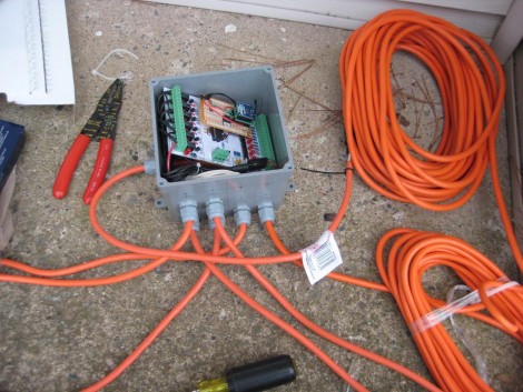
So what did he end up using this for? It was part of his Christmas light setup last year. The image above shows the PLC in a water-tight electrical box with extension cords running to each of the devices he wishes to control. The example code is what he used on the X-mas setup, but it should be enough of a guide to program this to work with just about any application.

USB Controller For Multiple Servos

USB_controller_for_6_servos

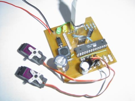
[dunk] constructed an easy to use AVR-based USB controller with the ability to drive up to six R/C hobby servos at once.  While the USB-powered Atmega8 he used supplies the necessary PWM signaling for all of the servos, an external power supply rated up to 30v at 3A is necessary to provide the 5v of power each servo requires.  His project is an extension of the USB servo controller built by [Ronald Schaten] and includes several significant upgrades.  The addition of 5 more servos aside, [dunk] switched to AVRlib routines for multi-servo control and PWM management, as well as added the aforementioned power supply to prevent an excessive current draw on the USB port.  His tutorial includes a complete parts list, Eagle PCB schematic, the required USB servo source code, as well as a sampling of commands that can be issued to the servo controller.

Reverse Engineering Radio Controlled Outlets

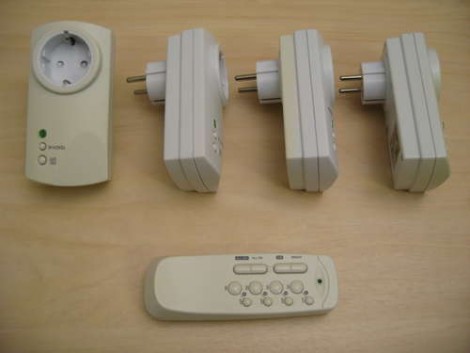
[Chr] picked up a pack of remote control outlets in order to reverse engineer them and build control into his own projects. These can be plugged into outlets around your house and a relay inside each module will switch whatever device is plugged into it after receiving a command from the remote. Once he cracked open the control housing it was easy to find the data line for the RF module which was on its own board. He used a logic analyzer to capture data from various button presses and then spent some time deciphering the communication protocol. He used what he learned to roll the module and code into an interface box where an ATmega8 connects via USB and passes commands from a computer to the RF board. Now he’s added home automation via a computer quite inexpensively. After the break you can watch a clip of the outlets switched using a smartphone.

So why not just patch into the buttons on the remote? Well, this same project was attempted at our local hackerspace earlier this month and the buttons don’t just pull a pin to ground. They use tri-state logic and are arranged into a matrix that is a lot harder to mimic (if not impossible) with a microcontroller. Analyzing the communications going into the RF module is definitely the less labor-intensive of the two approaches.

Continue reading “Reverse Engineering Radio Controlled Outlets”

Helicopter POV Display Is A Masterwork

helicopter hack LED mod

Yes! A radio control helicopter with a fairly high-resolution persistence-of-vision display is a beautiful thing. [Mziwisky’s] handiwork is the result of several steps along the prototyping path. He built up a POV test rig on a breadboard, designed his first PCB for the project, and then went to work building it. After initially being inspired by a POV ceiling fan [Mziwisky] looked around to see if anyone else had already added a display to a helicopter. Indeed, this has been done before but there were very few details on the build.

The helicopter has two blades and each have the same hardware on them and gobbled up about ten hours of assembly time each. He basically built a printed circuit board using the blades as a substrate by attaching adhesive copper foil. This makes up the matrix for the LEDs and connects to a small circuit board with an ATmega8 and some shift registers mounted on the inside end of the blade. There’s also a 180 mAh LiPo battery pack, and a hall effect sensor to synchronize the display on each. The results are spectacular, as you can see in the video after the break, but there’s a few bugs left to work out in order to fully tame the 32 LEDs on each rotor.

Kind of looks like the future is happening right now.

Continue reading “Helicopter POV Display Is A Masterwork”

R/C PPM Hacked

[Thomas Pfeifer] has taken the PPM signal produced by model aircraft wireless controllers, and with an ATMega8, converted the signal to act as a USB joystick. Which means you can now use a standard R/C remote control to fly model aircrafts on your computer. Of course now with PPM decoded you could also use the signal to control any electronic device. Like your mower, iPod, and we’ve even seen remote controlled pellet guns. Catch a video of [Thomas] flying a simulated quadrotor helicopter after the jump.

[Thanks Max]

Continue reading “R/C PPM Hacked”

USBasp: AVR Programmer Based On ATmega8

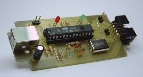
We love our AVR Dragon programmer but it can be nice to have a cheap and simple in system programmer on hand too. The USBasp is one such programmer that uses and ATmega8 as its only IC. It requires just a handful of components and can be purchased as a kit, or etched and assembled at home. If you source your own parts the chip does need to be programmed which makes for a chicken-or-egg scenario. We’ve used the Parallel-port dongle (schematic) from Adafruit’s Spoke POV before. It’s basically just a DAPA cable and a few resistors, a ribbon cable (use and old IDE cable if you have to) and a parallel port connector can have you up and running in no time. This is also a great way to get a friend into working with embedded systems. Order parts for a few of these and give them away to your buddies.

Dr. Boardman’s Color Conundrum

We feel like trumpets should be sounding. Someone took the overused project of connecting RGB LEDs to a microcontroller and produced something useful. [Paul] created Dr. Boardman’s Color Conundrum which works much like a simple mechanical coin-op game you might find at a carnival. When switched on, a random color is displayed by the ping-pong ball covered LED on the left. The player then manipulates three knobs to color-match the two lights.

Inside you’ll find a minimalist set of hardware. An ATmega8 polls the three potentiometers and uses them to mix the appropriate user color. Everything is wired-up using prototyping board and draws power from two AA batteries. He’s using a random seed stored in EEPROM and increments it every time the uC boots up. This keeps the input color different for every game.

Fun and simple, it’s not going to make your guests marvel at the complexity but [Paul’s] come up with a unique game that we think has marketing potential.