Toorcamp: Quadcopter Controlled By A TI-84+

What happens when you combine a TI-84+ graphing calculator with an added bluetooth module, a 1 Watt Alfa wifi dongle, and a Parrot Wifi Quadcopter? You get a long range quadcopter that’s controlled from the TI-84+ directional pad.

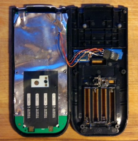
This TI-84+ looks like a standard issue school calculator, but [Owen] added an ATTiny13 microcontroller and a bluetooth module which sniffs the I/O port of the calculator. This allows for bi-directional communication with a laptop. He wrote a few Python scripts on the laptop to receive data from the calculator and send commands to the Parrot Quadcopter. The high-powered wifi module allowed for pretty good range with the Quadcopter, which was flown across the Toorcamp grounds.

Of course, having an innocent looking calculator with wireless communications has some other uses. Data could be displayed on the calculator from a phone over bluetooth. How about accessing Wikipedia or WolframAlpha from your calculator? Despite the possibilities, [Owen] did say that he’s never used it to cheat on tests.

Simple Proximity Sensor

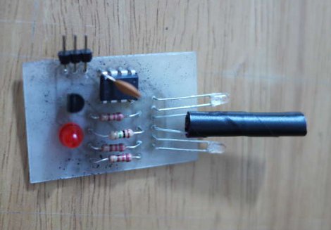
[Dustin Andrews] built this add-on board which works as a proximity sensor. He wanted a standalone sensor for his Arduino projects which would use a single pin as a trigger. This lets him alert the Arduino when an object approaches the sensor without the need for polling or extra code on the Arduino side of things.

As you can see, a single chip on the board takes care of all the work. That’s an ATtiny13, they’re inexpensive and sometimes you can even salvage them from consumer electronics like this color changing light bulb. The microcontroller monitors the phototransistor which is wrapped in electrical tape to isolate it from the IR LED emitters on either side. This setup creates a reflective sensor. When an object nears the board, the infrared light from the emitters reflects off of it and onto the phototransistor. And since the Arduino works as an AVR programmer you don’t need special hardware to program the device.

808 Camera Hack Produces A Time-lapse Tic Tac Box

It’s not really conceived as a spy cam, but it could be. [Quinn Dunki] built this tiny time-lapse camera project with racing in mind. She’s involved in a group that endurance races clunkers, and part of the fun is sharing the experience of riding around in the old beaters. The module seen above takes a picture every four seconds and will last 24 hours before needing new batteries or an SD card change. We wonder if that’s longer than some of the ‘racecars’ make it?

She picked up an 808 camera, which looks like the key fob you use to unlock your car doors. They’re so cheap you can include them in projects and not really care if you don’t get them back. Inside it’s got a small lithium battery, the circuit board with a processor, microSD card slot, and of course the SSD used to capture the images. To control the device she used a tiny relay with an ATtiny13 used for the timing. We think the battery selection is a bit overboard, but maybe the next version will be a little more conservative.

There was one folly along the way. She wanted to attach this to the body of the car with a handful of magnets. But they don’t play nicely with the magnetic relays so that was out. The solution was to add that lanyard ring to the case which will allow the camera to be zip tied to the vehicle. So far there are no time-lapse movies available, but keep your eyes on our links posts and we’ll try to include one when it pops up.

Building An EEPROM Programmer

Behold this ATtiny85 based EEPROM programmer. It seems like a roundabout way of doing things, but [Quinn Dunki] wanted to build to her specifications using tools she had on hand. What she came up with is an ATtinyISP USB programmer, pushing data to an ATtiny85, which then programs an EEPROM chip with said data.

The hardware is the next module for her Veronica 6502 computer build. When we last saw that project [Quinn] was planning to add persistent storage for the operating firmware. This will be in the form of an EEPROM programmed with this device. Using ISP and an ATtiny as a go-between means that she should have no problems reflashing the OS without removing the chip. But it all depends on how she designs the interface.

For example, she blew a whole bunch of time troubleshooting the device because garbage data was being written to the chip. In the end, having her manual bus programmer hooked up during the flashing operation was the culprit. Lesson learned, it’s onward and upward with the build.

We’ve been featuring [Quinn’s] projects a lot lately. That’s in part because they’re really interesting, but also because she does such a great job of documenting her experience.

Simple IR Sensor Simplifies Laptop Audio Control

tiny-ir-tv-remote-receiver

[Owen] has a fairly big project in the works, where he’ll need to use infrared light to send data wirelessly between two nodes. The only problem with his grand plan is that he has never built anything of the sort. As a learning exercise, he decided to try his hand at building a wireless control interface for his laptop, which he uses to play music while doing homework.

His laptop usually sits across the room from [Owen], where it is connected to a speaker and amplifier. He hates getting up repeatedly to change songs, so he figured he might as well build an IR receiver to control Winamp that responds to commands from his TV’s remote control. Using his Open Bench logic sniffer and an IR receiver from an old VCR, he deciphered his remote’s encoding system. He then programmed an ATtiny13 to decode messages received by the IR sensor, sending them to his laptop via USB.

He packaged things inside a tiny mint tin, which he hangs from a desk lamp while in use. Now he can easily perform just about any action in Winamp with a few button presses on his remote. [Owen] says that he’s incredibly happy with the results, and now that he has a firm grasp of IR signaling concepts, we can’t wait to see what he builds next.

Simple Circuit Reminds You To Lock The Door As You Rush Out Of The House

door_lock_minder

It seems that [pppd] is always rushing out of his apartment to catch the bus, and he finds himself frequently questioning whether or not he remembered to lock the door. He often doubles back to check, and while he has never actually forgotten to lock the door, he would rather not deal with the worry.

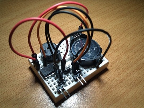
Since he finally had some free time on his hands, he decided to put together a simple device that would help end his worry once and for all. Using an ATtiny13, [pppd] designed a circuit that would detect when his door has been unlocked and opened, beeping every few seconds until the lock is reengaged. The circuit relies on a reed switch installed inside the door frame, which is tripped by the magnet he glued to his door’s deadbolt.

He says that the system works well so far, though he does have a few improvements in mind already.

Two Dice, One 8-pin UC

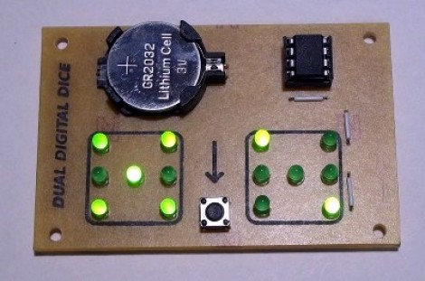
[Mike Shegedin] makes full use of an 8-pin microcontroller with this ATtiny13-based dice project. With a maximum of six I/O pins (that includes using the reset pin as I/O) he needed a couple of tricks in order to drive 14 LEDs and use a momentary push button for user input. We’re certainly familiar with the concepts here, but it still took quite a while to figure out what is going on with the schematic that [Mike] posted.

You’ve probably already guessed that he’s using Charlieplexing to drive more LEDs than he has pins. But when we started looking at the layout we thought he had drawn the schematic wrong, because there are six pairs of LEDs where the two diodes in each pair a not reverse biased, but hooked up in parallel. That, plus the fact that his battery is hooked up backwards. After several minutes of study the light bulb finally clicked on. Dice add pips (the dots on each side of a die) in pairs with the exception of the center pip. That means that you only need to control four total lines for each die (three pairs plus the center pip). There’s two ways to handle this, you could use four rows and two columns with traditional multiplexing, or you can reverse bias the two sets of LEDs for each die and use Charlieplexing. The former is a bit easier to program, the latter saves you one I/O pin and meant that [Mike] didn’t need to use the reset pin as I/O.

This is a clever addition to the collection of dice projects we’ve seen like the battery-less die, and the ATtiny2313 powered dice.