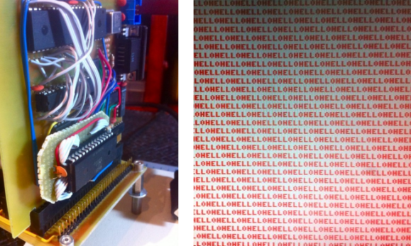
The screenshot on the right shows [Quinn Dunki’s] computer project displaying a Hello World program. Well, it’s only showing the word Hello right now, but the concept is the same. This proves that native 6502 code is running on the processor and reliably outputting data through its VGA hardware. That’s a welcome achievement after watching so much work go into this project.
But with anything this complex you can’t expect to make progress without finding bugs. And this step in the journey had a pretty big one in store for [Quinn]. After writing the assembly code and loading it into the machine she was dismayed to find that there were dropped characters all over the place. Now she shows a screenshot and says it’s easily recognizable as a race condition — proving she has a bigger brain than us.
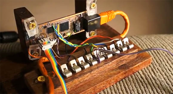
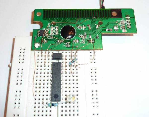
The problem is a pair of uninterruptible processes running on the same AVR chip (part of the GPU she built). They are fighting with each other for control of the processor cycles and she fixed it by making the daughter board seen in the image above. It moves one of the time-critical processes out of that single AVR chip to fix the issue by using an IDT7200L FIFO SRAM chip.