Hackaday Prize Entry: Optical Experiments Using Low Cost Lasercut Parts

Experimenting with optics can be great fun and educational. Trouble is, a lot of optical components are expensive. And other support paraphernalia such as optical benches, breadboards, and rails add to the cost. [Peter Walsh] and his team are working on designing a range of low-cost, easy to build, laser cut optics bench components. These are designed to be built using commonly available materials and tools and can be used as low-cost teaching tools for high-schools, home experimenters and hacker spaces.

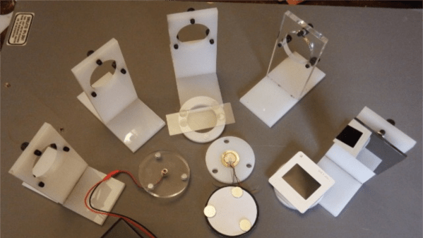
They have designed several types of holders for mounting parts such as lasers, lenses, slits, glass slides, cuvettes and mirrors. The holder parts are cut from ¼ inch acrylic and designed to snap fit together, making assembly easy. The holders consist of two parts. One is a circular disk with three embedded neodymium magnets, which holds the optical part. The other is the base which has three adjustment screws which let you align the optical part. The magnets allow the circular disk to snap on to the screws on the base.

A scope for improvement here would be to use ball plunger screws instead of the regular ones. The point contact between the spherical ball at the end of the screw and the magnet can offer improved alignment. A heavy, solid table with a ferrous surface such as a thick sheet of steel can be used as a bench / breadboard. Laser cut alignment rods, with embedded magnets let you set up the various parts for your experiment. There’s a Wiki where they will be documenting the various experiments that can be performed with this set. And the source files for building the parts are available from the GitHub repository.

Check out the two videos below to see how the system works.

Continue reading “Hackaday Prize Entry: Optical Experiments Using Low Cost Lasercut Parts”

DIY High Stability Timebase Hack For ~$25. Why? Frequency Stability Matters!

DIY High Stability Timebase OCXO

If you have an old “Racal-Dana 199x” frequency counter or similar 10 MHz internally referenced gear with a poor tolerance “standard quartz crystal oscillator” or bit better “temperature compensated crystal oscillator” (TCXO) you could upgrade to a high stability timebase “oven controlled crystal oscillator” (OCXO) for under $25. [Gerry Sweeney] shares his design and fabrication instructions for a DIY OCXO circuit he made for his Racal-Dana frequency counter. We have seen [Gerry] perform a similar upgrade to his HP 53151A, however, this circuit is more generic and can be lashed up on a small section of solderable perf board.

Oven controlled oscillators keep the crystal at a stable temperature which in turn improves frequency stability. Depending on where you’re starting, adding an OCXO could improve your frequency tolerance by 1 to 3 orders of magnitude. Sure, this isn’t as good as a rubidium frequency standard build like we have seen in the past, but as [Gerry] states it is nice to have a transportable standalone frequency counter that doesn’t have to be plugged into his rubidium frequency standard.

[Gerry’s] instructions, schematics and datasheets can be used to upgrade any lab gear which depends on a simple 10 MHz reference (crystal or TXCO). He purchased the OCXO off eBay for about $20 — it might be very old, yet we are assured they get more stable with age. Many OCXO’s require 5 V, 12 V or 24 V so your gear needs to accommodate the correct voltage and current load. To calibrate the OCXO you need a temperature stable variable voltage reference that can be adjusted from 1 to 4 volts. The MAX6198A he had on hand fit the bill at 5 ppm/°C temperature coefficient. Also of importance was to keep the voltage reference and trim pot just above the oven for added temperature stability as well as removing any heat transfer through the mounting screw.

You can watch the video and get more details after the break.

Continue reading “DIY High Stability Timebase Hack For ~$25. Why? Frequency Stability Matters!”

Turning A Rubidium Standard Into A Proper Tool

Rb

You can find rubidium frequency standards all over eBay and various surplus dealers. They’re actually quite interesting devices, able to generate a 10 MHz sine wave with enough precision to be a serviceable atomic clock. While these standards can find themselves very useful in a lab, they’re only a component, and not a working-out-of-the-box device. [Gerry] decided he would fix that, turning his rubidium standard into a proper piece of bench equipment, all in a single afternoon.

[Gerry]’s first step was finding a proper enclosure for his new piece of equipment. Most of the time, choosing an enclosure is practice in the art of compromise. This time, though, [Gerry] found the perfect enclosure: an old piece of video distribution equipment. On the back of this box, there are a ton of BNC plugs, perfect for attaching to random lab equipment and feeding them a signal from the rubidium standard.

After going through the video circuit and changing the 75 Ohm outputs to 50 Ohms, [Gerry] wired up an eBay power supply, fan, and a small circuit with an 8-pin PIC to complete his new tool. The rubidium standard does get freakishly hot, but hopefully mounting it to a large aluminum box with a bit of cooling will keep all the added electronics in working order.

[Gerry] did all this in just under 5 hours. An impressive feat, given that he probably spent that much time editing the video, available below.

Continue reading “Turning A Rubidium Standard Into A Proper Tool”

How To Take A Travelling Electronics Lab On The Road With You

If you’re a frequent traveler, or if you don’t have a garage or basement and find your kitchen table is doomed to serve most of its life as an electronics bench this hack is for you. [Robovergne] came up with a mobile electronics lab (translated) in order to help preserve the Wife Acceptance Factor for his hobby.

The project comes in two parts. On the right you see the pair of component storage cabinets. These are high-quality examples that fully enclose each drawer (cheaper cabinets are open at the back). This way, [Robovergne] was able to connect two of them together with a piano hinge, and add some carrying handles to the top.

The second half of the project is the bench itself. It features a lab supply, soldering iron transformer and holder, and some breadboards for good measure. The base of the unit houses a drawer which carries the bulk of his tools. Now he can pack up and clear out the living room in one single trip.

Function Generator Built And Mounted Inside Electronics Bench

A function generator is a handy piece of test equipment to have on-site. [Kammenos] designed and built his own function generator, using the bench itself as the enclosure. You can see above that the control panel presents a clean finished look. To achieve it, [Kammenos] designed and printed the panel labels on a sheet of paper, and used a piece of acrylic to protect it. The circuit inside uses a MAX038 high-frequency generator chip. This is a full-featured part that allows for great control based on a few external components. One of those is a selectable frequency range based on the capacitance value on one pin. This is selectable using a twelve-step rotary switch with a dozen different cap values. There’s also adjustment knobs for fine tuning, duty cycle, and DC offset.

Check out the video after the break for a full demonstration. If you want to build this yourself you’ll need to do some chip hunting. The MAX038 is obsolete. You may still be able to find one, but at around $20 you should be able to source a replacement with the same features and save yourself cash all in one step.

Continue reading “Function Generator Built And Mounted Inside Electronics Bench”

Bench Supply With Current Limiting

This is a bench power supply with adjustable voltage and current limiting. [Sylvain’s] creation can regulate 0-25 volts while sourcing 0-5 amps. Current limiting is a nice feature as it will allow you to test your prototypes to ensure the power regulator you choose will not be over or underpowered.

This supply is really a two-in-one. The case has two separate circuits so that you can have different power rails going at the same time. There is a microcontroller involved, but the ATmega32 doesn’t do anything more than measure the voltage and amperage and drive the graphic LCD screen. Two potentiometers are responsible for setting the voltage and limiting the current.

[Thanks Sargonout]