Open Source High Speed SiGe IC Production For Free!

We’ve covered the Tiny Tapeout project a few times on these pages, and while getting your digital IC design out there onto actual silicon for a low cost is super cool, it is still somewhat limited. Now, along comes the German FMD QNC project funding MPW (multi-project wafer) runs not in bog standard Silicon CMOS but Silicon-Germanium bipolar technology. And this is accessible to you and me, of course, provided you have the skills to design in this high-speed analog technology.

The design can be submitted via Github by cloning the IHP-Open-DesignLib repo, adding your design, and issuing a pull request. If your submission passes the correctness checks and is selected, it will be fabricated in-house by the IHP pilot line facility, which means it will take at least four months to complete.  However, there are a few restrictions. The design must be open source, DRC complete (obviously!) and below a somewhat limiting two square millimetres. Bonus points for selecting your project can be had for good documentation and a unique quality, i.e., they shouldn’t have too many similar designs in the project archive. Also, you don’t get to keep the silicon samples, but you may rent them for up to two years for evaluation. In fact, anybody can rent them.  Still, it’s a valuable service to trial a new technique or debug a design and a great way to learn and hone a craft that is difficult to get into by traditional means. Such projects would be an excellent source of verifiable CV experience points we reckon!

If you fancy getting your hands on your own silicon, but bipolar SiGe is a bit of a stretch, look no further than our guide to Tiny Tapeout. But don’t take our word for it—listen to the creator himself!

The Imperfect Bipolar Transistor

We like to pretend that our circuit elements are perfect because, honestly, it makes life easier and it often doesn’t matter much in practice. For a normal design, the fact that a foot of wire has a tiny bit of resistance or that our capacitor value might be off by 10% doesn’t make much difference. One place that we really bury our heads in the sand, though, is when we use bipolar transistors as switches. A perfect switch would have 0 volts across it when it is actuated. A real switch won’t quite get there, but it will be doggone close. But a bipolar transistor in saturation won’t be really all the way on. [The Offset Volt] looks at how a bipolar transistor switches and why the voltage across it at saturation is a few tenths of a volt. You can see the video below.

To understand it, you’ll need a little bit of math and some understanding of the construction of transistors. The idea of using a transistor as a switch is that the transistor is saturated — that is, increasing base current doesn’t make much change in the collector current. While it isn’t perfect, it is good enough to switch a relay or do other common switching tasks.

Continue reading “The Imperfect Bipolar Transistor”

Bipolar Bot For Drawing Spirals

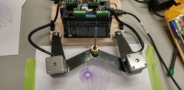
[Bart Dring] is well known around these parts for Makerslide, the buildlog.net laser cutter, and a collaboration with Inventables for the Carvey CNC machine. They’re all popular projects and all very useful. This one, not so much. It’s a bipolar bot that doesn’t take itself too seriously, and this year’s build for [Bart]’s usual gonzo CNC machine for ORD Camp.

The Bipolar Bot – yes, that’s its name – is pretty much a SCARA bot. There are two NEMA 14 steppers in the joint of two arms, each of which are bolted to a bearing on a base plate with the other end holding a pen. That’s it as far as the mechanics go, but the software is extremely interesting.

The steppers are driven by an Arduino with the help of a tool that converts Cartesian Gcode to the bipolar Gcode the machine requires. There’s a bit of math involved, but nothing of note if you can code some trig functions

Right now the bipolar bot is busy drawing stuff that looks like it came right off a spirograph. You can see a video of that below.

Continue reading “Bipolar Bot For Drawing Spirals”

Fixing A Multimeter’s Serial Interface

[Shane] bought a multimeter with the idea of using its serial output as a source for data logging. A multimeter with a serial port is a blessing, but it’s still RS-232 with bipolar voltage levels. Some modifications to the meter were required to get it working with a microcontroller, and a few bits of Python needed to be written, but [Shane] is getting useful data out of his meter.

The meter in question is a Tenma 72-7735, a lower end model that still somehow has an opto-isolated serial output. Converting the bipolar logic to TTL logic was as easy as desoldering the photodiode from the circuit and tapping the serial data out from that.

With normal logic levels, the only thing left to do was to figure out how to read the data the meter was sending. It’s a poorly documented system, but [Shane] was able to find some documentation for this meter. Having a meter output something sane, like the freaking numbers displayed on the meter would be far too simple for the designers of this tool. Instead, the serial port outputs the segments of the LCD displayed. It’s all described in a hard to read table, but [Shane] was able to whip up a little bit of Python to parse the serial stream.

It’s only a work in progress – [Shane] plans to do data logging with a microcontroller some time in the future, but at least now he has a complete understanding on how this meter works. He can read the data straight off the screen, and all the code to have a tiny micro parse this data.

Super Nice CNC Router Build Leaves Little To Be Desired

Aluminum CNC Router
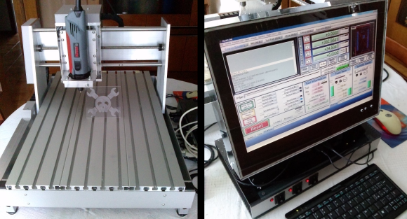
[Enzo] wrote in to tell us about his recently completed CNC Router (translated). This is an excellent high-quality, all-aluminum build with no cut corners. The work envelope is a respectable 340 by 420 mm with 80 mm in the Z direction. Linear ball bearings make for smooth travel and lead screws with both axial and radial bearings give a solid foundation of accurate and repeatable movements.

Aluminum CNC Router

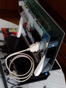
We’ve had a bunch of CNC Router projects on Hackaday in the past, including other nicely made aluminum ones, but [Enzo] is the only one who spent just as much effort on his computer and machine control system as he did on the CNC machine itself. The computer, which is running Windows and Mach3, is an all-in-one style build that starts out with an old LCD screen from a broken laptop. Along with the reused screen, a very small ETX form factor motherboard was stuffed inside a custom made plexiglass enclosure. A Compact Flash card handles the storage requirements.

Underneath the monitor is another great looking custom made enclosure which houses the stepper motor drivers. There are 3 switches on the front panel to send main’s power out to the PC, spindle and an AUX for future use. On the back panel there are D-sub connectors for each stepper motor, the limit switches and the PC connection. Oh yeah, by the way [Enzo] designed his own bipolar motor drivers (translated) and sent the design out for fabrication. These boards use an A4989 IC and mosfets to control the motors. The schematics are on his site in case you’d like to make some yourself.

Continue reading “Super Nice CNC Router Build Leaves Little To Be Desired”

Changing Unipolar Steppers To Bipolar

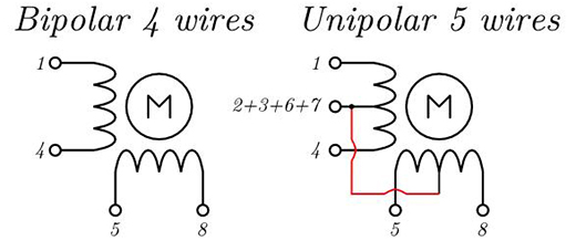
If you’ve been a good little hacker and have been tearing apart old printers like you’re supposed to, you’ve probably run across more than a few stepper motors. These motors come in a variety of flavors, from the four-wire deals you find in 3D printer builds, to motors with five or six wires. Unipolar motors – the ones with more than four wires – are easier to control, but are severely limited in generating torque. Luckily, you can use any unipolar motor as a more efficient bipolar motor with a simple xacto knife modification.

The extra wires in a unipolar motor are taps for each of the coils. Simply ignoring these wires and using the two coils independently makes the motor more efficient at generating torque.

[Jangeox] did a little experiment in taking a unipolar motor, cutting the trace to the coil taps, and measuring the before and after torque. The results are impressive: as a unipolar motor, the motor has about 380 gcm of torque. In bipolar mode, the same motor has 800 gcm of torque. You can check that video out below.

Continue reading “Changing Unipolar Steppers To Bipolar”