Solder Trick To Make Your Own Surface Mount Breakout Boards

surface-mount-breakout-trick

We think you’re really going to enjoy this trick for making surface mount breakout boards. It’s common to use magnet wire to connect individual pins of a surface mount part to breadboard friendly protoboard with pin headers. What’s new here (at least to us) is that [Raul] solders one wire to both pins directly across from one another.

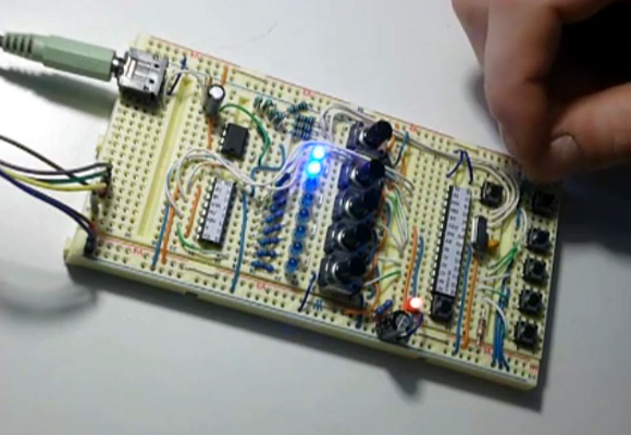
The image at the left shows an eight pin part with four wires soldered in place. To get to this point he first taped the wires down to a work surface being careful to space them to match the pitch on the chip’s leads. He then tapes the chip in place and solders all of the legs to the wires. This seems to kill two birds with one stone as aligning one wire to one leg is tough. From there he flips the chip over and cuts the wire spanning under it. This leaves an easy job of soldering the trailing side of the wire to a hunk of protoboard.

It’s perfect for chips with a small number of pins. Of course you may still want an etched breakout board for something with a ton of leads.

Building A Synth On A Breadboard

synth

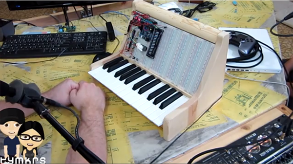
Building an analog synth is a challenge, but with the [Tymkrs] protosynth, it’s easier than ever. It’s a 25-key keyboard attached to a stack of solderless breadboards to make analog synth prototyping a snap.

Earlier, [Tymkrs] acquired a whole bunch of solderless breadboards and decided to put them to use by making a component-level modular synth. The earlier incarnation tied each key on the keyboard to a few wires behind the breadboard and tied them in to a shift register so they could be read with a Propeller dev board loaded up with a Commodore SID emulator. The new version keeps the very clean through-the-back keyboard connector, but this time the [Tymkrs] are adding a few more components that add a sequencer setup and a rotary encoder.

The eventual goal for this really cool breadboard synth is to explore the world of Moogs, Arps, and other analog synths easily on a breadbaord. The [Tymkrs] have already put together a breadboard-compatible low pass and high pass filter. While there’s still a lot of work to be done to make an analog synth a reality, the [Tymkrs] are off to a great start.

Continue reading “Building A Synth On A Breadboard”

Retrotechtacular: Donner 3500 Portable Analog Computer

What if we told you we had a computer you can take with you? What if it only weighed 28 pounds? This is a pretty hard sell when today you can get a 1.5 GHz quad-core processor packing computer to carry in your pocket which weighs less than 5 ounces. But back in the day the Donner 3500 was something to raise an eyebrow at, especially for tinkerers like us.

The machine was unveiled in 1959 as an analog computer. Instead of accepting programs via a terminal, or punch cards, it worked more like a breadboard. The top of the case features a grid of connectors (they look like banana plugs to us but we’re not sure). The kit came with components which the user could plug into the top to make the machine function (or compute) in different ways.

We’re skeptical as to how portable this actually was. It used vacuum tubes which are not fans of being jostled. Still, coming during the days when most computers were taking up entire buildings we guess the marketing claim holds up. If you’d like to see a bit more about the machine’s internals check out this forum post.

Breadboard Friendly FPGAs

Regular Hackaday readers will be familiar with all the cool things you can do with FPGAs; emulating old video game consoles, cracking encryption protocols, and DIY logic analyzers become relatively simple projects with even a modest FPGA dev board on your workbench. Many FPGA boards aren’t geared towards prototyping, though, and breadboard friendly devices are hard to come by. Here’s a pair of breadboardable FPGAs we’ve found while searching for some related hardware over the past few days

First up is the Mercury FPGA Module. Packaged in a DIP-64 format, the Mercury features a Spartan-3A FPGA with the equivalent of 200k logic gates. Elsewhere on the board is 512kB of RAM and 128kB of Flash storage. There are enough GPIO pins for nearly any project, but sadly only a 10-bit ADC – the same resolution you’d find in an AVR or PIC ‘micro.

Of course the Mercury isn’t the only breadboard-friendly FPGA dev board out there. There’s also the slightly more capable XuLA2 board powered by a Spartan-6 with 32 MB of RAM, 1MB of Flash. Unlike the Mercury, the XuLA2 can also fit in one of those ‘half-sized’ solderless breadboards.

Yes, it’s a different form factor than the commonly recommended Papilio One or the DE0. If you can suggest any other ‘beginners’ (i.e. doesn’t cost an arm and a leg) FPGA boards, leave a note in the comments and we’ll summarize them in another post.

Make Dual Pin Header Footprints Into Breadboard Friendly DIP

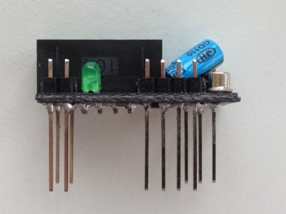
[John] wrote in with a solution to a prototyping issue that has vexed us for quite some time. Above you can see the DIP friendly solution for dual-row pin headers which he came up with. With just a bit of easy soldering he now has a breadboard friendly device for prototyping.

He starts by soldering a dual row pin header on the board, then clips off all of the legs on the outside row. The row of legs that remain are then inserted into one side of the trench on his breadboard. The other side of the trench has a single row pin header, and he solders them to the outer row on the breakout board using another single pin header aligned horizontally. This isn’t a 100% convenient solution, as it’s still pretty hard to get your jumper wires in the breadboard on the side covered by the breakout board. But if you plan in advance you can place your wires first, then plug in the development board.

Here [John] is working with TI’s eZ430-RF2500 board. We’d like to go back and remove the dual pin socket we soldered on our eZ430-F2013, replacing it with this style of pins.

Breadboarding With A 144-core Processor

At the center of that green PCB is a tiny little processor with way too many cores. It’s the GA144 which was taken for a test-drive on a breadboard by [Andrew Back]. We saw a multi-core Kickstarter project last month. This will cost a lot less and get you more than twice the number of cores. But as was mentioned in the comments on that post, the drawback is the programming language. This chip’s IDE uses Forth.

There is a dev board available, but [Andrew] went instead with a QFN-to-Through-Hole adapter board which he hand soldered. Once he has access to the pins the chip can be programmed with an FTDI adapter which is compatible with the 1.8V logic levels. The provided Forth IDE (arrayForth) is a Windows only program but it does run under Wine. We followed the project through to see him twiddling I/O pins. But we still have trouble thinking of applications for it. In a world of complex and inexpensive FPGA chips, what would you use this type of processor for?

Breadboarding A 4-bit ALU

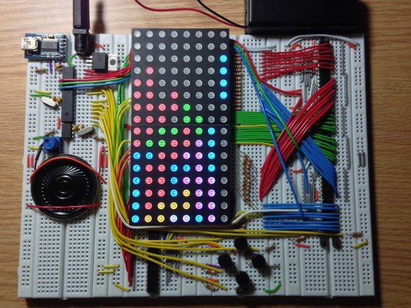
[TGTTGIT] recently took the plunge and decided to build his own computer using logic chips. He just completed a 4-bit ALU which can compute 18 functions. It took a long time to get the wiring right, but in true geek fashion his build was accompanied by an alternating Chapelle’s Show and Star Trek: TNG marathon playing in the background.

This project is the stepping stone for a larger 16-bit version. The experience of wiring up just this much of it has convinced him that an FPGA is the only way to go for the future of the build. But since he had already ordered the chips it was decided that the only thing to do was to see this much through. He used the truth table from The Elements of Computing Systems for the design and posted several times about the project before arriving at this stopping point so you may be interested in clicking through the other post on his blog. There’s also a lot of other TTL computer projects around here worth checking into.

Continue reading “Breadboarding A 4-bit ALU”