The Easiest Way To Dive In To ARM Programming

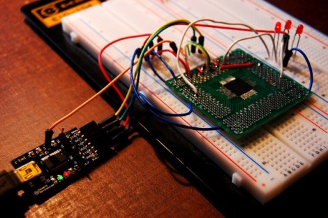
[Brad] has been very excited about an ARM Cortex-M0 chip released by NXP; it’s a fully featured ARM microcontroller, and is, quite amazingly, stuffed into a hobbyist and breadboard-friendly DIP-28 package. After finding a supplier for this chip, [Brad] dove in and put together a great tutorial for programming an ARM on the breadboard using open source tools.

The chip in question is NXP’s LPC1114FN28, a 28-pin breadboard friendly chip we’ve posted about before. After finding a single supplier for this microcontroller (only $1.26 for one chip!), [Brad] pulled out his breadboard and started wiring things up.

Because this microcontroller has an on-board oscillator, wiring up a breadboard and putting in a breakout for an FTDI cable was a snap. After configuring a toolchain and writing a bit of code, the only issue was uploading the code to the chip. This was handled by the lpc21isp programming tool, slightly modified and configured by [Brad] to support his favorite microcontroller.

The LPC1114FN28 is an impressive bit of kit, and with free tools to program the damn thing, we can’t wait for a homebrew ARM dev board to show up.

ProtoSynth, The Prototyping Synthesizer

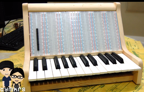
This project isn’t really a prototype, but a tool for prototyping. [Tymkrs] came up with a unique way to build this synthesizer prototyping tool. They actually patched into the underside of the breadboards in order to keep all of the permanent bits nice and tidy.

In the clip after the break you’ll see all of the build photos that lead up to this point. After cutting out and assembling the wooden pieces for the case they grab a soldering iron and get to work. Two octaves worth of keys were pulled out of an electric keyboard. Ribbon cable is soldered onto each key’s electrical connection, with an SIL pin header as a connector. This mates with another ribbon cable with a SIL socket on one end, and an IDC connector on the other. The real trick is getting that IDC connected to the breadboard. They cut back the adhesive tape on the underside of the board and soldered a surface mount pin header onto it. This way the inputs from the keys, as well as a few 1/4″ jacks from the back of the case are always available in a tidy way on the breadboards. The video goes on to show preliminary synthesizer work on the device.

Continue reading “ProtoSynth, The Prototyping Synthesizer”

Switch Mode Breadboard Supply From A PTH08080

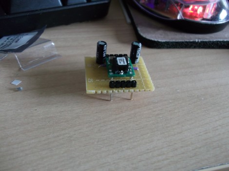
[Ben] wanted a switch mode power supply for his breadboard. He ordered a PTH08080 module which is made by Texas Instruments. The spec sheet would make it a great choice for him, but he was not happy to learn that the pinout doesn’t conform to the 0.1″ spacing used by solderless breadboards. His solution was to make a breakout adapter from some protoboard.

The PTH08080 can source up to 2.25A. It accepts 4.5-18V input and can output 0.9-5.5V. The best part is the efficiency that a switch mode supply achieves compared to linear regulators. This design adds in two capacitors which are suggested in the application circuit from the datasheet (PDF). Notice that there are two headers on the breakout board. One supplies power and ground to the breadboard. The other gives him a place to connect the adjustment resistor used to select the output voltage. This connects between one pin on the PTH08080 and GND. [Ben] plans to upgrade the design by included a precision trimpot for easy output voltage adjustments.

One Enormous Breadboard

[Franklyn] wrote in to tell us about the The Hack Factory Big Board project. The Twin Cities Maker group, a Minneapolis/St Paul based hackspace, set out to provide an education tool to help students make the leap from schematic diagrams to bread board connections.   Naturally their conclusion was to create a humungous 10x scale bread board.  The board features scaled up yet fully functional capacitors, resistors, a dip switch, and the jumbo-est LEDs we’ve seen in a long while.

Like its 0.1″ pitch counterpart, passive components can be thrown in 1″ pitch breadboard to create a myriad of analog circuits. The Twin Cities folks even tossed together an optical theremin using a scaled up photoresistor.  Beyond analog circuits the board can also demonstrate various ICs using either a custom breakout board featuring an 8-pin DIP socket or a vacuum formed Atmega 328 which boasts an internal Arduino Uno. The cool thing about the giant 28-pin DIP is that it does not necessarily function as a microcontroller.  Instead the UNO will be loaded with chip emulation programs geared towards the lesson at hand,  jumpers  select programs to teach debouncing, logic, flip-flops, and a whole slew of other basic concepts.

We are a bit concerned that the next logical step is a gigantic soldering iron,  but at least we finally have something to interface to the huge liquid crystal display.  If you still want more giant circuit stuff check out this 555 footstool.

Check out a quick intro video after the jump!

Continue reading “One Enormous Breadboard”

Ancient Laptop Given New Life As Mobile Prototyping Platform

What can you do with a broken Compaq SLT 286? Its briefcase-like size and shape actually make for a pretty interesting portable electronic prototyping station. [Philip] gutted the components and started adding back the items he most commonly uses when developing a project.

He shares all of the details in the video after the break. At center stage is a double breadboard where the keyboard would normally be found. It’s hard to make out in the image above, but there is a set of terminal strips running vertically to either side of these breadboards. Each terminal is connected to a peripheral or power/ground bus. The black knob to the left lets him adjust the output of a variable voltage regulator. To the lower right there’s a rotary encoder, push button, toggle switch, and a couple of potentiometers. These, along with the keypad and character display (mounted where the screen used to be) and DB connectors (on the back of the case) have their pins mapped to the terminal block to the right. [Philip] has mounted an Arduino Uno over the area to the bottom left, but we’re sure that it’s pretty easy to swap out for just about any breakout board he needs.

To answer [Philip’s] running dialog from the video: no, it is not the worst demo ever. We think you did a great job demonstrating all the features. Loose connections are par for the course when it comes to prototypes.

Continue reading “Ancient Laptop Given New Life As Mobile Prototyping Platform”

BB313 Breadboard Platform Makes ATtiny Prototyping Painless

Johngineer's BB313

[John De Cristofaro aka Johngineer] uses various ATmega microcontrollers in his electronics projects, but he finds himself reaching for an ATtiny2313 or ATtiny4313 more often than not. He got tired of having to wire up pin headers, capacitors, and the like each time he started a project, so he spent some time designing an easy to use breadboard platform around the chips.

Inspired by LadyAda’s Boarduino, his BB313 board features FTDI pin headers, an ISP programming header, a reset button, along with breakout pins that plug directly into any breadboard. Aside from sharing a similar layout, [John] says that the similarities end there. His board is designed for designers who program in C or C++, so Arduino code won’t run without some substantial modification.

The board looks like a pretty handy benchtop tool, and we’re pretty sure it would be a big time saver for anyone who uses these chips with any frequency. [John] says that the board cost about $6.50 to make when he put it together, but that prices might vary slightly depending on where you have your PCBs made.

Be sure to swing by his site if the design looks like it might be helpful. He has made the schematics, a bill of materials, and all the rest available for the taking.

[via Adafruit blog]

Another Take On Using ‘dead’ Batteries

Here’s another circuit that can be used to squeeze the remaining potential from supposedly dead batteries. Just like the AASaver, we see this as a useful prototyping tool, providing juice for a breadboard even though it’s not reliable enough for long-term use (the batteries are just about through after all).

First off, the image above shows rechargeables instead of alkalines. We don’t recommend this as the circuit has no cutoff feature and the 0.7V input for the boost converter surely is below the recommended low-voltage limit for those cells. But that aside, we like the diminutive board which solders onto the end of a battery pack. It uses an SC120SKTRT which is a variable boost regulator capable of outputting 1.8-5V depending on resistor choices. You can leave the resistors off and it will default to 3.3V, set the output explicitly, or roll in some potentiometers and use your multimeter to tune the output.

This regulator costs more than the MCP1640 used in the AASaver, but it appears to use less passive components making for a smaller footprint. At a total of $3.50 plus the PCB (which will be a snap to etch at home) this is another great option to top off your next parts order.

[Thanks Uwe]