flipflop_clock

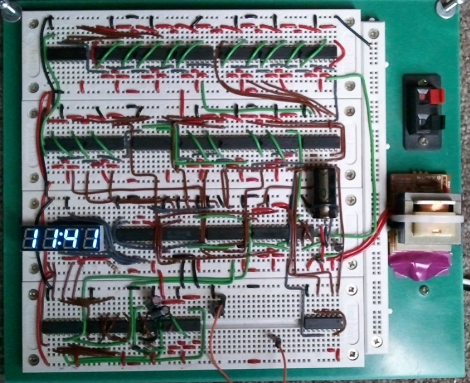
FlipFlop Clock Uses Mains Frequency To Keep Time

One afternoon, [Sam] was a bit bored and decided he would build a clock. Not wanting to spend any money on the project, he set off to construct his clock using only the components he had on hand – this meant no micro controllers would be used whatsoever.

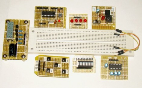
Built on a set of four breadboards, his clock sports a pretty short parts list. It uses just over a dozen flipflops, a few NAND chips, a 555 timer, and a small handful of other components. What you won’t find on the bill of materials however, is any sort of crystal or real-time clock. Instead of using a separate chip for keeping time, he opted to use the 60hz mains frequency as the basis for his time keeping.

The mains sine wave is passed through a series of frequency dividers to reach a 1/60hz signal, which is used to trigger the clock counters he constructed. The time is displayed on a 4-digit seven segment display, using a pair of multiplexers clocked by a 555 timer.

The clock seems to work nicely, though you have to be pretty well-versed in how the clock was built to set the time. The only means of doing so is to probe into the clock of the digit you are setting while pressing the lone pushbutton mounted on the breadboard.

While we are pretty sure no one will ever mess with his clock’s time, we have to wonder if it blinks on and off like our old VCR when the power goes out.

Circuit Building With A Hammer And Nails

real_breadboarding

[Collin Cunningham] over at Make recently wrapped up another edition of “Collin’s Lab” – this time around, the subject is breadboards. He starts off by discussing a common solderless breadboard, something you are no doubt familiar with. What you might not know however is how breadboards got their name.

Way back when, before there was a RadioShack in every strip mall across the country, fancy prototyping supplies like your solderless breadboard did not exist. Amateur radio operators would prototype circuits on wooden boards, often using whatever was around as a substrate. Many times, this meant that the family’s cutting board ended up as a makeshift prototyping station.

One popular method of building circuits was to drive small nails into the breadboard, using wire wrapping to connect things together. [Collin] demonstrates this technique in the video, constructing a simple LED flasher circuit.

He says that the process works decently enough, and was kind of fun to do. He does mention however that building any sort of circuit requiring an IC would likely be out of the question.

If you have a few minutes to spare, check out the video embedded below – [Collin’s] take on technology is quirky and entertaining as always.

Continue reading “Circuit Building With A Hammer And Nails”

AVR HVSP On A Tiny Breadboard

AVR chips are convenient because you can program them in circuit at their operating voltage. That is, unless you screw up the fuse settings and they’ll no longer listen to an In System Programmer. If you find yourself facing this problem, just build this circuit on a breadboard and ‘unbrick’ by holding down the button.

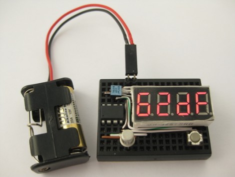
The circuit seen above is a High Voltage Serial Programmer. This is one of two high voltage protocols used by AVR chips; HVSP is for chips that don’t have enough pins to use High Voltage Parallel Programming. This rendition uses a 12V power source, which is the level necessary for the high voltage method. A 7805 linear regulator joins the mix to provide operational voltage, along with one transistor, an ATtiny2313 to control the circuit, a four-digit 7-segment display for feedback, and one button for control.

Watch the video after the break to see an ATtiny13 programmed to disable the reset pin using a breadboarded programmer. That chip is then easily rescued, having been automatically recognized by using its device signature.

Continue reading “AVR HVSP On A Tiny Breadboard”

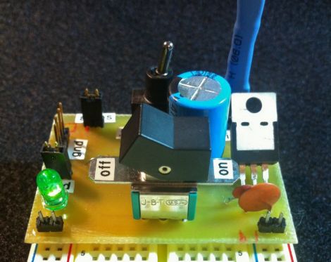
Button Cell Connectors For Breadboarding

We’re working on a project that has a battery backup, but we don’t have any more coin cell holders on hand. No problem, we remember seeing a double pin header used for this. But when we tried to shove the CR2032 battery in between the pins it was a no-go. We could swear we’d featured a project that does this but couldn’t find it here at Hackaday. After much searching we came up with the Guerrilla battery holder which is seen on the left. No wonder it wasn’t working, the CR1212 in that picture is a much smaller package. So we figured we’d have to come up with something else, until inspiration struck.

There must be some other way to configure the pin header to work with a fatter cell body. On the right you can see that a diagonal orientation works like a charm. Join us after the break for a couple of close-ups of that connector and our thoughts on using this with a variety of different cells.

Continue reading “Button Cell Connectors For Breadboarding”

5×2 Patch Board

Sometimes we want to sit on the back porch, crack a beer, and do some prototyping. Other times we’d like to do the same but on the couch in the livingroom. To that end we added a 5×2 pin to 10×1 pin patch board to our solderless breadboard.

The 5×2 pin form factor is pretty common, used as an AVR programming header, on development boards like the Dragon Rider 500 and the STK 500, and in small prototyping devices like the Bus Pirate. We like the freedom of using IDC cables as interconnects and that’s where this board comes in. Now we can patch into the IDC cables yet still quickly disconnect them when moving to a different prototyping location. Check out the PCB artwork and this handy device in use after the break.

Continue reading “5×2 Patch Board”

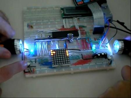
Binary Clock Uses DS3232 RTC

[Kenneth Finnegan] quenches our clock-a-day compulsion with his Arduino based binary timepiece. The clock uses a 5×7 LED matrix as a display and shows month, day, and time. He sourced a DS3232 real-time clock which automatically compensates for temperature to achieve very accurate time keeping. We like the super-cap circuit he added to keep the RTC running if the power is cut.

Is an Arduino overkill here? Well, the code is certainly not filling the 16k available on the ATmega168. At $4.32, the $1-2 you could save by using a lower-grade chip is not worth having to rewrite the code developed during prototyping. [Kenneth] also mentions that these projects usually only hang around for a few weeks before they’re re-purposed for the next endeavor.

Take a look at [Kenneth’s] superb hardware walk through in the video after the break.  If you’re a fan of clean breadboarding, he’s also made a time-lapse of the circuit building process.

Continue reading “Binary Clock Uses DS3232 RTC”

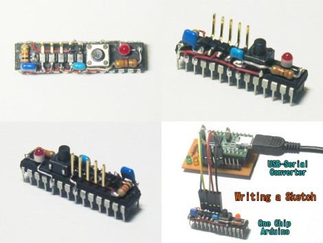
The Day After Arduino

There will come a day in every budding hacker’s life that they realize that plopping an entire arduino in their project and leaving it there is a bit of a waste. [Domiflichi] realized this, and has shared his next steps with us. He takes us through the process of removing the ATMega chip and breadboarding it for final use.

For many of you, this is an obvious chain of events. However, there are also many who just haven’t ventured forward and taken this one step that will forever change how their projects are seen by the hacking world.  For the anti-arduino crowd, realize that this is an opportunity not to bash a useful tool but to help nurture and lead people to the next step.