Restoring A Vintage CGA Card With Homebrew HASL

Right off the bat, we’ll stipulate that what [Adrian] is doing in the video below isn’t actual hot air solder leveling. But we thought the results of his card-edge connector restoration on a CGA video card from the early 80s was pretty slick, and worth keeping in mind for other applications.

The back story is that [Adrian], of “Digital Basement” YouTube fame, came across an original IBM video card from the early days of the IBM-PC. The card was unceremoniously dumped, probably due to the badly corroded pins on the card-edge bus connector. The damage appeared to be related to a leaking battery — the corrosion had that sickly look that seems to only come from the guts of batteries — leading him to try cleaning the formerly gold-plated pins. He chose naval jelly rust remover for the job; for those unfamiliar with this product, it’s mostly phosphoric acid mixed with thickeners and is used as a rust remover.

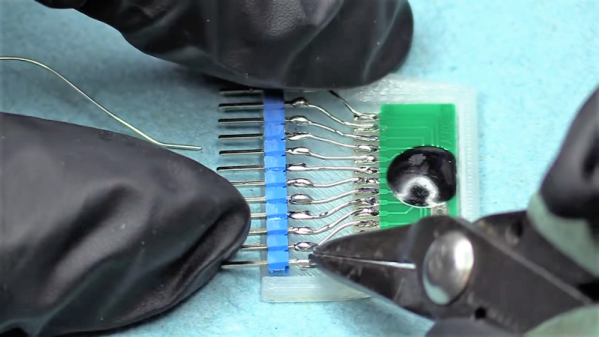
The naval jelly certainly did the trick, but left the gold-plated pins a little worse for the wear. Getting them back to their previous state wasn’t on the table, but protecting them with a thin layer of solder was easy enough. [Adrian] used liquid rosin flux and a generous layer of 60:40 solder, which was followed by removing the excess with desoldering braid. That worked great and got the pins on both sides of the board into good shape.

[Adrian] also mentioned a friend who recommended using toilet paper to wick up excess solder, but sadly he didn’t demonstrate that method. Sounds a little sketchy, but maybe we’ll give it a try. As for making this more HASL-like, maybe heating up the excess solder with an iron and blasting the excess off with some compressed air would be worth a try.

Continue reading “Restoring A Vintage CGA Card With Homebrew HASL”

This Debug Connector Brings Your Issues To The Edge

Given an unknown PCBA with an ARM processor, odds are good that it will have either the standard 10 pin 0.05″ or 20 pin 0.1″ debug connector. This uncommon commonality is a boon for an exploring hacker, but when designing a board such headers require board space in the design and more components to be installed to plug in. The literally-named Debug Edge standard is a new libre attempt to remedy this inconvenience.

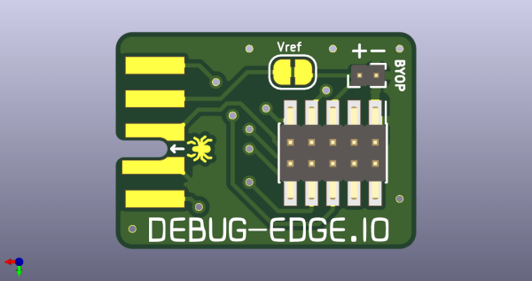
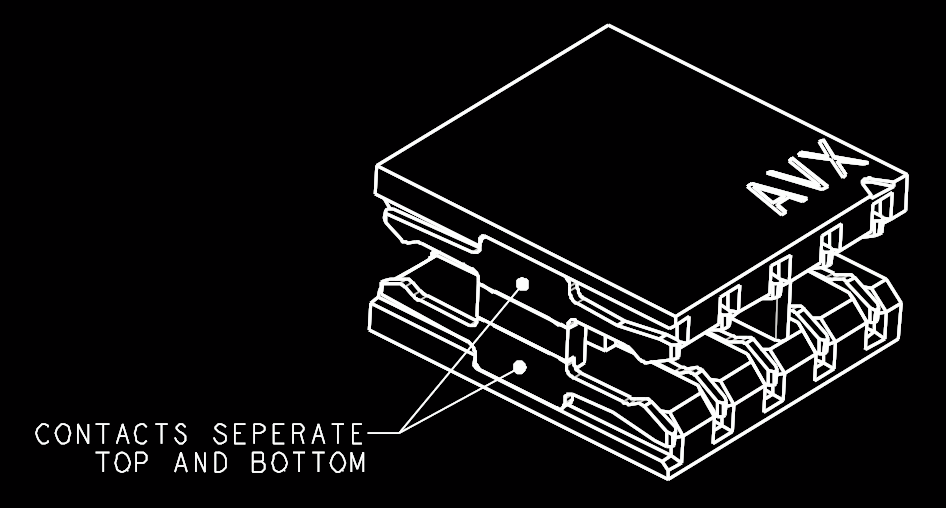
The name “Debug Edge” says it all. It’s a debug, edge connector. A connector for the edge of a PCBA to break out debug signals. Card edge connectors are nothing new but they typically either slot one PCBA perpendicularly into another (as in a PCI card) or hold them in parallel (as in a mini PCIe card or an m.2 SSD). The DebugEdge connector is more like a PCBA butt splice.

It makes use of a specific family of AVX open ended card edge connectors designed to splice together long rectangular PCBAs used for lighting end to end. These are available in single quantities starting as low as $0.85 (part number for the design shown here is 009159010061916). The vision of the DebugEdge standard is that this connector is exposed along the edge of the target device, then “spliced” into the debug connector for target power and debug.

Right now the DebugEdge exists primarily as a standard, a set of KiCAD footprints, and prototype adapter boards on OSHPark (debugger side, target side). A device making use of it would integrate the target side and the developer would use the debugger side to connect. The standard specifies 4, 6, 8, and 10 pin varieties (mapping to sizes of available connector, the ‘010’ in the number above specifies pincount) offering increasing levels of connectivity up to a complete 1:1 mapping of the standard 10 pin ARM connector. Keep in mind the connectors are double sided, so the 4 pin version is a miniscule 4mm x 4.5mm! We’re excited to see that worm its way into a tiny project or two.

We’ve seen plenty of part-free debug and programming connectors before. Have a favorite? Let us know in the comments!

A Hacked Solution For Non-Standard Audio Modules

When life hands you lemons, lemonade ends up being your drink of choice. When life hands you non-standard components, however, you’ve got little choice but to create your own standard to use them. Drinking lemonade in such a situation is left to your discretion.

The little audio record and playback modules [Fran Blanche] scored from eBay for a buck a piece are a good example. These widgets are chip-on-board devices that probably came from some toy manufacturer and can record and playback 20 seconds of audio with just a little external circuitry. [Fran] wants to record different clips on a bunch of these, and pictured using the card-edge connector provided to plug them the recording circuit. But the pad spacing didn’t fit any connector she could find, so she came up with her own. The module and a standard 0.1″ (2.54 mm) pitch header are both glued into a 3D-printed case, and the board is connected to the header by bonding wires. It makes a nice module that’s easily plugged in for recording, and as [Fran] points out, it’s pretty adorable to boot. Check it out in the video below.

Sure, the same thing could have been accomplished with a custom PCB breaking out the module’s pins to a standard card-edge connector. But [Fran] knows a thing or two about ordering PCBs, and our guess is she wanted to get this done with what was on hand rather than wait for weeks. There’s something to be said for semi-instant gratification, after all. And lemonade.

Continue reading “A Hacked Solution For Non-Standard Audio Modules”

Local Hacker Discovers Card Edge Connectors

When [turingbirds] was looking around for the absolute minimum connector for a JTAG adapter, he wanted something small, that didn’t require expensive adapters, and that could easily and reliably connect a few JTAG pins to a programmer. This, unsurprisingly, is a problem that’s been solved many times over, but that doesn’t mean there isn’t room for improvement. [turingbirds] found his better solution by looking at some old card edge connectors.

Instead of 0.1″ pitch pin headers, weirder and more expensive connectors, the Tag Connect, or even pogo pins, [turingbirds] came up with a JTAG adapter that required no additional parts, had a small footprint, and could be constructed out of trash usually found behind any busy hackerspace or garage. The connector is based on the venerable PCI connector, chopped up with a Dremel and soldered to a JTAG or ISP programmer.

This is simply a card edge connector, something the younglings seem to have forgotten. Back in the day, card edge connectors were a great way to connect peripherals, ports, and anything else to the outside world. They were keyed, and you could only put them in one way. They were relatively cheap, and with a big coil of ribbon cable, you could make custom adapters easily. For low-speed connections that will only be used a few times, it’s very hard to beat a card edge connector.

Of course the connector itself is only half of the actual build. To turn a chopped up PCI connector into a JTAG adapter, [turingbirds] made footprint and part files for his favorite PCB design tool. In this case it’s Eagle, and the libraries that will plop one of these connectors down are available on GitHub.

Is this the latest and greatest way to plug a programmer into a board? No, because this has been around for 30 or 40 years. It does, however, put a programming port on a PCB with zero dollars in components, a minimum of board footprint, and uses parts that can be salvaged from any pile of old computers.

Fixing An NES For Good

Sometime in the late 80s, the vast collective consciousness of 8-year-olds discovered a Nintendo Entertainment System could be fixed merely by blowing on the cartridge connector. No one knows how this was independently discovered, no one knows the original discoverer, but one fact remains true: dirty pins probably weren’t the problem.

The problem with a NES that just won’t read a cartridge is the ZIF socket inside the console. Pins get bent, and that spring-loaded, VCR-like front loader assembly is the main point of failure of these consoles, even 30 years later. You can get replacement ZIF sockets for a few bucks, and replace the old one using only a screwdriver, but this only delays the inevitable. That ZIF socket will fail again a few years down the line. Finally, there is a solution.

The Blinking Light Win, as this project is called, replaces the ZIF connector with two card-edge slots. One slot connects to the NES main board, the other to the cartridge connector. There’s a plastic adapter that replaces the spring-loaded push down mechanism created for the original ZIF connector, and installation is exactly as easy as installing a reproduction NES ZIF connector.

If you’re wondering why consoles like the SNES, Genesis, and even the top-loader NES never had problems that required blowing into the cartridge connector, it’s because the mere insertion of the cartridge into the slot performed a scrubbing action against the pins. Since the ZIF socket in the O.G. NES didn’t have this, it was prone to failure. Replacing the ZIF with a true card-edge slot does away with all the problems of dirty contacts, and now turns the NES into something that’s at least as reliable as other cartridge-based consoles.