Cheap GPS units are readily available nowadays, which is great if you have something that needs to be very precisely located. Finding the position of things is one of many uses for GPS, though. There are plenty of ways to take advantage of some of the ancillary tools that the GPS uses to determine location. In this case it’s using the precise timekeeping abilities of the satellites to build a microsecond-accurate network time protocol (NTP) server.
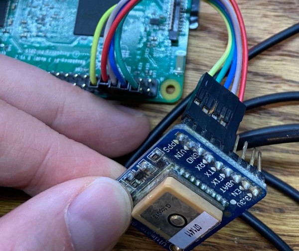
GPS works by triangulating position between a receiver and a number of satellites, but since the satellites are constantly moving an incredibly precise timing signal is needed in order to accurately determine location from all of these variables. This build simply teases out that time information from the satellite network and ignores the location data. There are only two parts to this build, a cheap GPS receiver and a Raspberry Pi, but [Austin] goes into great detail about how to set up the software side as well including installing PPS, GPSd, and then setting up the actual NTP server on the Pi.
While this is an excellent way to self-host your own NTP server if you don’t have Internet access (or just want to do it yourself), [Austin] does note that this is probably overkill on timekeeping as far as accuracy goes. On the other hand, the Raspberry Pi has no built-in real time clock of its own, so this might actually be a cost-competitive way of timekeeping even when compared to something more traditional like a DS3231 RTC module.