Bolts, Brass, And Machining Chops Make Up This Tiny Combination Safe

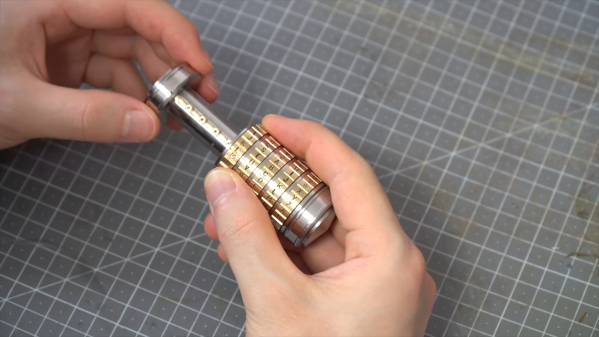
Another day, another video that seriously makes us doubt whether eschewing the purchase of a lathe in favor of feeding the family is a value proposition. This time, [Maker B] shows us what the queen of machine tools can do by turning a couple of bolts into a miniature safe.

We’ll state right up front that this build doesn’t source all its material from a single bolt. It’s more like two bolts and a few odd pieces of brass, but that doesn’t detract from the final product one bit. [Maker B] relieves the two chunky stainless steel bolts of their hex heads and their threads on the lathe, forming two nesting cylinders with a satisfyingly tight fit. A brass bar is machined into a key that fits between slots cut in the nesting cylinders, while discs of brass form the combination dials. Each disc is stamped around its circumference with the 26 letters of the alphabet; we thought the jig used for stamping was exceptionally clever, and resulted in neat impressions. The combination, which is set by placing a pin next to a letter in each disc, protects the admittedly limited contents of the tiny safe, but functionality is hardly the point. This is all about craftsmanship and machining skills, and we love it.

If you’ve sensed an uptick in resource-constrained builds like this lately, you’re not alone. The “one bolt challenge” has resulted in this wonderfully machined combination lock, as well as the artistry of this one-bolt sculpture. We’re all in favor of keeping the trend going. Continue reading “Bolts, Brass, And Machining Chops Make Up This Tiny Combination Safe”

Color-Coded Key Opens Doors, Opportunities

Of all the ways to open up a lock, there are some tried and true methods. Keys, combinations, RFIDs, picks, and explosives have all had their time and place, but now someone else wants to try something new. [Erik] has come up with a lock that opens when it is shown a pattern of colors.

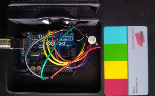
The lock in question uses a set of color coded cards as the “keys”. When the cards are inserted in the lock, a TCS230 color sensor interprets the pattern on the cards and sends the information over to an Arduino Uno. From there, the Arduino can command the physical lock to open if the pattern is a match, although [Erik] is still waiting on the locking mechanism to arrive while he continues to prototype the device.

This is a fairly unique idea with a number of upsides. First, the code can’t be “stolen” from inside a wallet like RFID cards can. (Although if you can take a picture of the card all bets are off.) If you lose your key, you can simply print another one, and the device is able to handle multiple different keys and log the usage of each one. Additionally, no specialized equipment is needed to create the cards, unlike technologies that rely on magnetic strips. Of course, there’s always this classic way of opening doors if you’d rather go old school with your home locks.

Continue reading “Color-Coded Key Opens Doors, Opportunities”

Master Lock Auto-cracker Built As Coursework At University

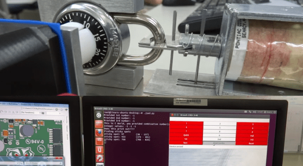
We love the beginning of May because the final projects for college coursework start rolling into our tips line. Here’s one of the latest, it’s an automatic Master lock combination cracker which was built by [Ross Aiken] and his classmates as part of their ECE453 Embedded Microprocessor System Design class at the University of Wisconsin – Madison.

We’ve talked about the ease with which these locks can be cracked. But [Ross] points out that the resources we linked to before are flawed. To get the combination as quickly as possible the team has implemented an algorithm discussed here. Their machine uses a stepper motor to turn the dial with a big solenoid to pull on the shackle. The system is sensitive enough to detect the “sticky” spots of the lock, which are then used to narrow the number of possible combinations before brute forcing the combination. As you can see in the video after the break, the shackle moves slightly when pulled after an incorrect combination. The long vertical pin near the solenoid will pass through an optical sensor when the correct combination is found.

Do you have your own final project to show off? What are you waiting for, send us a tip about it!

Continue reading “Master Lock Auto-cracker Built As Coursework At University”

Ultrasonic Combo Lock

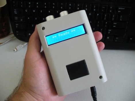
[John Boxall] took a different route for a single-input combination lock. This unit uses a Ping ultrasonic range finder to input a four digit code. It’s a hardware upgrade, but uses the same basic concept as his button-based combo lock. That design used an Arduino to measure how long you hold down a single button, with a one second pause between inputs, to enter the code. This one also uses timing to establish when each digit is read, but that digit is grabbed as the distance between your hand and the sensor.

There are things we like and dislike about the redesign. This is obviously much more expensive than other button-based locks like this garage door opener we built. If we were to run with [John’s] design, we might spring for the Ping sensor (because it’s a pretty cool input) and replace he character LCD with an LED or two. The other drawback that we see here is that it may be easy for someone to steal your code by watching from afar. Still, we love the project and think you will too after seeing the demo clip below.

Continue reading “Ultrasonic Combo Lock”

Doorbell Combo Lock Can Open Your Garage Door

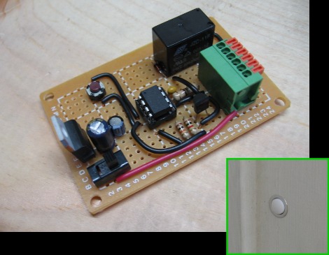
Sometimes I get enough away from writing about other people’s accomplishments long enough to actually do my own hacks. Most recently I developed a combination lock that opens the garage door. The idea isn’t original, it is based on [Alan Parekh’s] button code project, but I did develop my own hardware and software. A four digit code is entered by pressing the button a number of times for the first digit, and waiting for a flash of an LED inside before moving on to the next digit. If the correct code is entered the door opens.

My version centers around an ATtiny13. I originally downloaded [Alan’s] code in hopes that I could port the PIC firmware over pretty easily. Unfortunately it was written in BASIC so I just took what I knew about the interface and wrote my own program. I developed on an ATmega168 so that I would have no trouble running out of programming space, and was able to optimize my code down to 964 bytes to fit on the tiny13.

The hardware is quite simple. I purchased a lighted doorbell from Home Depot and swapped out the light bulb for an LED. I choose this because the doorbell mounts in a 5/8″ hole in the trim of the garage door and is easily overlooked. I’m quite happy with the results, and if you want to play around with the idea, you can easily build the circuit on a breadboard and use another LED for the load rather than including a relay. Hit the link at the top of this post for the schematic, code, and build images.