You’ve probably seen tweezers act as test probes for a multimeter or other instrument. Some electronics testing tweezers even have the multimeter built right in. Tools like these are especially handy for working with surface mount components. [Bweed2] found a probe made by E-Z hook that kept a fixed distance you can set with a thumbwheel. It looked good, but the $70-$80 price tag seemed too much.
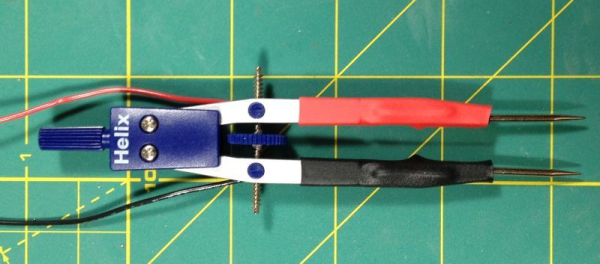
Employing hacker ingenuity, he turned to a drafting compass. You know, the tool you use to draw circles. He picked up one for about $10 and then got some cheaper compasses to scavenge their needles (the compass usually only has one needle since the other side holds a pencil). The result was a useful set of adjustable probes.
Once you have the idea, it is a pretty simple project. Immobilize the knee of the compass with glue, connect some wires and–for extra points–add some red and black heat shrink to make it pretty.
Want to make a more classic SMD tweezer? Here’s one we’ve covered before. If you’d rather use your feet and your ears with your probes, you might be interested in these.