On the heels of our post on retro-Soviet transistor teardowns and die-shots, [nikitas] wrote in to tell us about a huge thread on rare vacuum devices of all varieties: oddball cathode-ray tubes, obscure Nixies, and strange Soviet valves. We thought the other forum post was overwhelming at just over 110 pages, but how about 391 pages (and counting) of blown-glass electronics?
If you read through the decaptholon, we mentioned that a particularly enthusiastic poster, [lalka], looked to be cataloguing every Soviet oscillator circuit. It turns out that he’s also the one behind this incredible (random) compendium of everything that’s had the air sucked out of it.
The modern office has become a sea of LCD monitors. It’s hard to believe that only a few years ago we were sitting behind Cathode Ray Tubes (CRTs). People have already forgotten the heat, the dust, and the lovely high frequency squeal from their flyback transformers.
Image by Søren Peo Pedersen via wikipedia
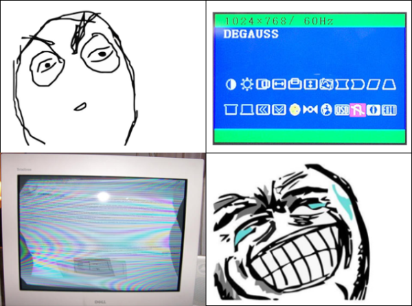
There was one feature of those old monitors which seems to be poorly understood. The lowly degauss button. On some monitors it was a physical button. On others, it was a magnet icon on the On Screen Display (OSD). Pressing it rewarded the user with around 5 seconds of a wavy display accompanied by a loud hum.
But what exactly did this button do? It seems that many never knew the purpose of that silly little button, beyond the light-and-sound show. The truth is that degaussing is rather important. Not only to CRTs, but in many other electronic and industrial applications.
Of Shadow Masks and Aperture Grilles
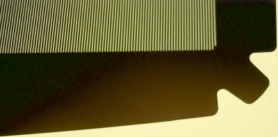
Close up of a shadow mask by Rauenstein via Wikipedia
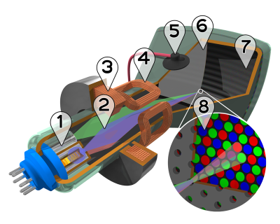
A CRT has quite a few components. There are three electron guns as well as steering and convergence coils at the rear (yoke) of the tube. The front of the tube has a phosphor-coated glass plate which forms the screen. Just behind that glass is a metal grid called the shadow mask. If you had enough money for a Sony screen, the shadow mask was replaced by the famous Trinitron aperture grille, a fine mesh of wires which performed a similar function. The shadow mask or aperture grille’s job is to ensure that the right beams of electrons hit the red, green, or blue phosphor coatings on the front of the screen.
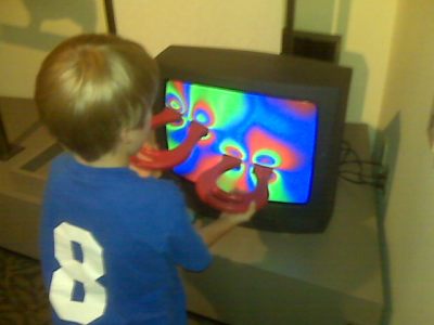
This all required a very precise alignment. Any stray magnetic fields imprinted on the mask would cause the electron beams to bend as they flew through the tube. Too strong a magnetic field, and your TV or monitor would start showing rainbows like something out of a 1960’s acid trip movie. Even the Earth’s own magnetic field could become imprinted on the shadow mask. Simply turning a TV from North to East could cause problems. The official term for it was “Color Purity”.
These issues were well known from the early days of color TV sets. To combat this, manufacturers added a degaussing coil to their sets. A coil of wire wrapped around the front of the tube, just behind the bezel of the set. When the set was powered on, the coil would be fed with mains voltage. This is the well-known ‘fwoomp and buzz’ those old TV sets and monitors would make when you first turned them on. The 50 Hz or 60 Hz AC would create a strong moving magnetic field. This field would effectively erase the imprinted magnetic fields on the shadow mask or aperture grille.
Running high current through the thin degaussing coil would quickly lead to a fire. Sets avoided this by using a Positive Temperature Coefficient (PTC) thermistor in-line with the coil. The current itself (or a small heating coil) would heat up the PTC, causing resistance to increase, and current through the coil to drop. After about 5 seconds, the coil was completely shut down, and the screen was (hopefully) degaussed.
As time went on monitors became embedded systems. The PTC devices were replaced by transistors controlled by the monitor’s main microcontroller. Monitor manufacturers knew that their sets were higher resolution than the average TV set, and thus even more sensitive to magnetic fields. Users are also more likely to move a monitor while using it. This lead the manufacturers to add a degauss button to the front of their sets. A push of the button would energize the coil for a few seconds under software control. Some monitors would also limit the number of times a user could push the button, ensuring the coil didn’t get too hot.
Holding a magnet near the front of a black and white (or a monochrome ‘green screen’) CRT created visible distortion, but no lasting damage. Mid-century hackers who tried the same trick with their first color TV quickly learned that the rainbow effect stayed long after the magnet was moved away. In extreme cases like these, the internal degaussing coil wouldn’t be strong enough to clear the shadow mask.
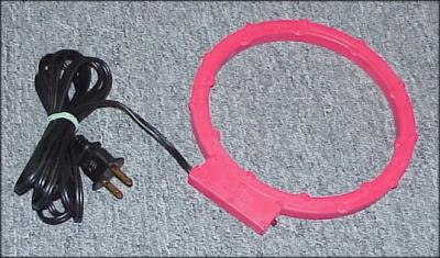
Commercial degaussing coil
When all else failed, a handheld degaussing coil or wand could be used. Literally waving the magic wand in front of the screen would usually clear things up. It was of course possible to permanently damage the shadow mask. Back in 2007, I was working for a radar company which had been slow to switch to LCD monitors. Being a radar shop, we had a few strong magnetron magnets lying around. One of these magnets was passed around among the engineers. Leaving the magnet under your monitor overnight would guarantee rainbows in the morning, and a shiny new LCD within a few days.
Queen Mary, showing her degaussing coil
CRTs aren’t the only devices which use degaussing coils. The term was originally coined in 1945 by Charles F. Goodeve of the Royal Canadian Naval Volunteer Reserve (RCNVR). German mines were capable of detecting the magnetic fields in a naval ship’s steel hull. Coils were used to mask this field. The Queen Mary is one of the more famous ships fitted with a degaussing coil to avoid the deadly mines.
Even mechanical wristwatches can benefit from a bit of degaussing. A watch which has been magnetized will typically run fast. Typically this is due to the steel balance spring becoming a weak magnet. The coils of the spring stick together as the balance wheel winds and unwinds each second. A degaussing coil (or in this case, more properly a demagnetizer) can quickly eliminate the problem.
A story on degaussing wouldn’t be complete without mentioning magnetic media. Handheld or tabletop degaussing coils can be used to bulk erase floppy disks, magnetic tape, even hard disks. One has to wonder if the degaussing coils in monitors were responsible for floppy disks becoming corrupted back in the old days.
So there you have it. The magic degaussing button demystified!
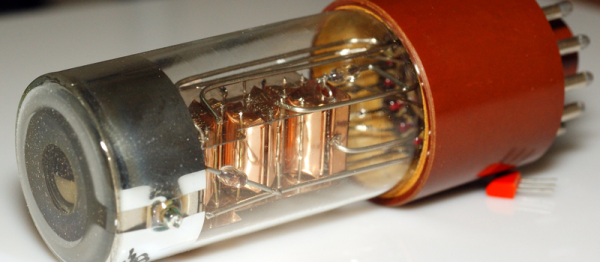
In a lifetime of working with electronics we see a lot of technologies arrive, become mighty, then disappear as though they had never been. The germanium transistor for instance, thermionic valves (“tubes”), helical-scan video tape, or the CRT display. Along the way we pick up a trove of general knowledge and special skills associated with working on the devices, which become redundant once the world has moved on, and are suitable only reminiscing about times gone by.
When I think about my now-redundant special skills, there is one that comes to the fore through both the complexity and skill required, and its complete irrelevance today. I’m talking about convergence of the delta-gun shadow mask colour CRTs that were the height of television technology until the 1970s, and which were still readily available for tinkering purposes by a teenager in the 1980s. Continue reading “My Most Obsolete Skill: Delta-Gun Convergence”→
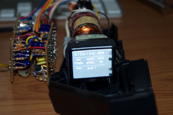
[Kevin] wanted to make something using a small CRT, maybe an oscilloscope clock or something similar. He thought he scored big with a portable black and white TV that someone threw away, but it wouldn’t power on. Once opened, he thought he found the culprit—a couple of crusty, popped capacitors. [Kevin] ordered some new ones and played with the Arduino TVout code while he waited.
The caps arrived, but the little TV still wouldn’t chooch. Closer inspection revealed that someone had been there before him and ripped out some JST-connected components. Undaunted, [Kevin] went looking for a new CRT and found a vintage JVC camcorder viewfinder on the electronic bay with a 1-1/8″ screen.
At this point, he knew he wanted to display the time, date, and temperature. He figured out how the viewfinder CRT is wired, correctly assuming that the lone shielded wire is meant for composite video. It worked, but the image was backwards and off-center. No problem, just a matter of tracing out the horizontal and vertical deflection wires, swapping the horizontal ones, and nudging a few pixels in the code. Now he just has to spin a PCB, build an enclosure, and roll his own font.
The reports of the death of the VGA connector are greatly exaggerated. Rumors of the demise of the VGA connector has been going around for a decade now, but VGA has been remarkably resiliant in the face of its impending doom; this post was written on a nine-month old laptop connected to an external monitor through the very familiar thick cable with two blue ends. VGA is a port that can still be found on the back of millions of TVs and monitors that will be shipped this year.
This year is, however, the year that VGA finally dies. After 30 years, after being depreciated by several technologies, and after it became easy to put a VGA output on everything from an eight-pin microcontroller to a Raspberry Pi, VGA has died. It’s not supported by the latest Intel chips, and it’s hard to find a motherboard with the very familiar VGA connector.
The Vectrex is a rare beast in the world of retro video games. Introduced in 1982, this was the only video game system to put a monitor right in the console, and it did so for good reason. This was a games system with vector graphics and rotating 3D objects, something that just couldn’t happen on the TV in the family room. A while ago, [John] dug his old Vectrex out of his basement and replaced a faulty logic board. The CRT was still broken, but with a little bit of research and a not-so-ugly kludge, he managed to replace the CRT in a Vectrex.
[John] found someone willing to part with an old CRT online, and after whipping out his credit card, the tube was on his way to his front door. This new tube wasn’t a direct drop in; The original Vectrex had small ears around the edges of the screen that served as mounting points. The new tube had no such ears. Now, a bit of plastic strapping holds the CRT in the chassis. It’s a bit of a kludge, but at least now [John] has a source of Vectrex CRTs.
While the rest of [John]’s repair work didn’t go as well – the Vectrex in question still has all the logic board problems it had when it was taken out of storage. This Vectrex does have a new CRT, and with a bit more work on rehabbing this old machine, it should keep on working for another thirty years.
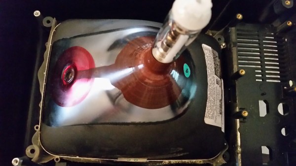
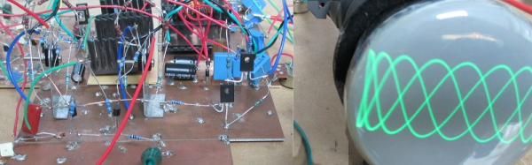
[GK] had some old CRTs lying around, so naturally he decided to build an old school analog scope with one of them. Lucky for us, he’s been documenting his progress. Since it was a big project to tackle, he started out with Spice modeling to work out all the right values.
Prototyping the power supply took some custom transformer winding, but when done, the power supply did the job. Although he’s still wiring up the Z (intensity) axis, the scope is already capable of displaying signals and even text characters using a character generator he built earlier (see video below).
[GK] spends most of the time so far talking about the high voltage power supply design. For the particular tubes he had on hand he needed +200V, -400V, -550V, and 6.3VAC for the CRT heater. This is certainly not the typical Arduino-based digital scope that everyone builds at least once.
 These issues were well known from the early days of color TV sets. To combat this, manufacturers added a degaussing coil to their sets. A coil of wire wrapped around the front of the tube, just behind the bezel of the set. When the set was powered on, the coil would be fed with mains voltage. This is the well-known ‘fwoomp and buzz’ those old TV sets and monitors would make when you first turned them on. The 50 Hz or 60 Hz AC would create a strong moving magnetic field. This field would effectively erase the imprinted magnetic fields on the shadow mask or aperture grille.