Scope Noob: Microcontroller Quirks With DDS

In this installment of Scope Noob I’m working with Direct Digital Synthesis using a microcontroller. I was pleasantly surprised by some of the quirks which I discovered during this process. Most notably, I had a chance to look at errant triggers solved by using holdoff and a few timing peculiarities introduced by my use of the microcontroller. Here’s a video synopsis but I’ll cover everything in-depth after the break.

Continue reading “Scope Noob: Microcontroller Quirks With DDS”

Direct Digital Synthesis (DDS)

Direct Digital Synthesis (DDS) Explained By [Bil Herd]

One of the acronyms you may hear thrown around is DDS which stands for Direct Digital Synthesis. DDS can be as simple as taking a digital value — a collection of ones and zeroes — and processing it through a Digital to Analog Converter (DAC) circuit. For example, if the digital source is the output of a counter that counts up to a maximum value and resets then the output of the DAC would be a ramp (analog signal) that increases in voltage until it resets back to its starting voltage.

This concept can be very useful for creating signals for use in a project or as a poor-man’s version of a signal or function generator. With this in mind I set out here to demonstrate some basic waveforms using programmable logic for flexibility, and a small collection of resistors to act as a cheap DAC. In the end I will also demonstrate an off-the-shelf and inexpensive DDS chip that can be used with any of the popular micro-controller boards available that support SPI serial communication.

All of the topics covered in the video are also discussed further after the break.

Continue reading “Direct Digital Synthesis (DDS) Explained By [Bil Herd]”

Digital “Crystal” Breathes New Life Into Old Radio

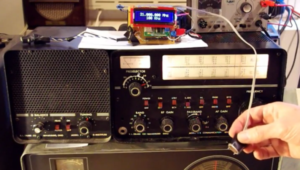
[Bill Meara] of the Soldersmoke Podcast has a nice old Drake 2B radio, and wanted to use it for the 12 meter amateur band. These old radios normally make switching tuning bands easy — you just swap out one frequency crystal for another and you’re set.

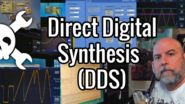
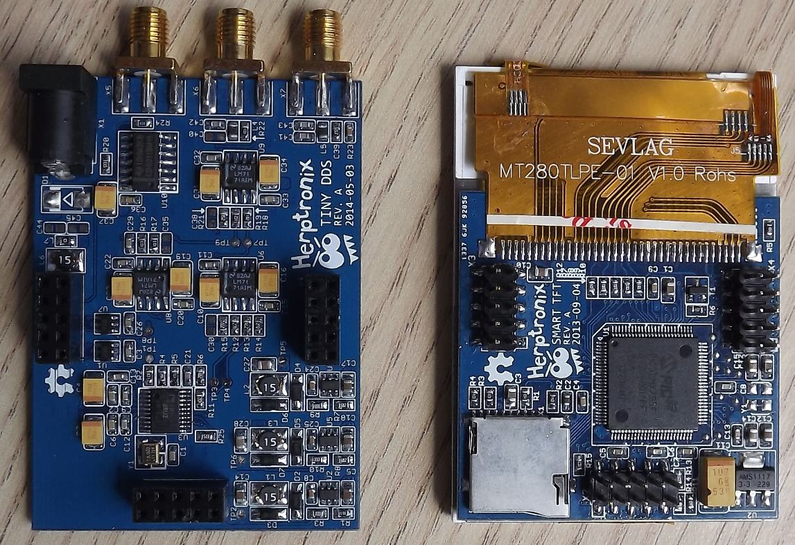
Only [Bill] didn’t have the 21 MHz crystal that he needed. No problem, because he had a junk crystal, a hacksaw, and a modern direct-digital synthesis (DDS) chip sitting around. So he takes the donor crystal, cuts it open, and solders the two wires directly from the DDS to the crystal’s pins. Now he’s got a plug-in replacement digital oscillator that doesn’t require modifying the nice old Drake receiver at all. A sweet little trick.

The video’s a little bit long, but the money shot comes in around 5:00.

Now, one might worry about simply plugging a powered circuit (the DDS) in place of a passive element (the crystal), but it seems to work and the proof of the pudding is in the tasting. We wonder how far this digitally-controlled-analog-receiver idea could be extended.

An Open Source 1MHz Arbitrary Waveform Generator With An Awesome UI

1MHZ DDS


[Herp] just shared a nice 1MHz Arbitrary Waveform Generator (right click -> translate to English as google translation links don’t work) with a well designed user interface. His platform is based around a PIC32, a TFT module with its touchscreen and the 75MHz AD9834 Direct Digital Synthesizer (DDS). Of course the latter could generate signals with frequencies up to 37.5MHz… but that’s only if two output points are good enough for you.

As you can see in the video embedded below, the ‘tiny dds’ can generate many different kinds of periodic signals and even ones that are directly drawn on the touchscreen. The offset and signal amplitude can be adjusted using several operational amplifiers after the DDS ouput and a separate SMA TTL output is available to use a PIC32 PWM signal. The platform can read WAV audio files stored on microSD cards and also has an analog input for signal monitoring. Follow us after the break for the video.

Continue reading “An Open Source 1MHz Arbitrary Waveform Generator With An Awesome UI”

Adorable Homebrew Waveform Generator

waveform

For want of new test equipment, or simply a project, [Enzo] decided he would take a shot at creating his own waveform generator*. Not only is it a great project, it’s also a decent piece of test equipment, with proper signal conditioning, a nice front panel, and a built-in wall transformer.

The guts of [Enzo]’s waveform generator is an AD9833 programmable waveform generator, a neat little chip that can output square and triangle waves fro 0.1 Hz to 3.2 MHz and sine waves from 0.1 Hz to 1.6 MHz. [Enzo] is controlling this chip with a PIC16 microcontroller, with a whole bunch of analog circuitry between the digital domain and the BNC connector on the front panel.

The waveform generator is controlled by a suite of dials and switches on the front panel, giving [Enzo] complete control over his new tool.

* Here’s a Google translation, but good luck with that. Just… get Chrome or something.

AVR DDS Signal Generator Improvements

[Vassilis Papanikolaou] took a good thing and made it better with some design upgrades to this AVR based signal generator. We looked at version 1.0 of this tool back in 2006 and since then it saw an upgrade to 2.0. But [Vassilis] wanted to take things one step further, with a compact single-sided PCB. What you see above is the beautiful result of his work; a professionally made board that is compact, uses through-hole components, and has zero wire jumpers.

If you want to build one for yourself there’s a great parts list as well as board artwork and schematic. The system uses an ATmega16 so you’ll need a way to program one. There’s also just a bit of firmware tweaking to remap the control buttons to match the updated hardware layout.