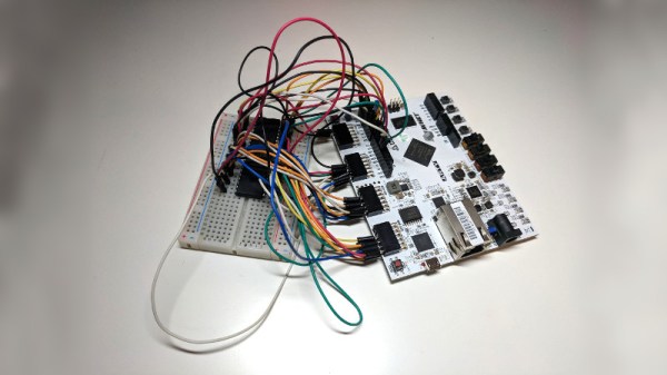
The hackers over at Radiona.org, a Zagreb Makerspace, have been hard at work designing the ULX3S, an open-source development board for LATTICE ECP5 FPGAs. This board might help make 2019 the Year of the Hacker FPGA, whose occurrence has been predicted once again after not quite materializing in 2018. Even a quick look at the board and the open-source development surrounding it hints that this time might be different.
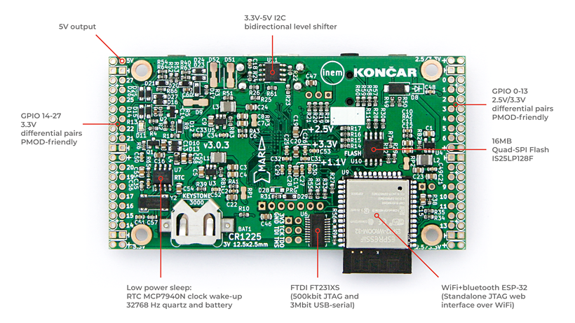
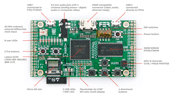
The ULX3S was developed primarily as an educational tool for undergraduate-level digital logic classes. As such, it falls into the “kitchen sink” category of FPGA boards, which include a comprehensive suite of peripherals and devices for development, as opposed to more bare-bones FPGA breakouts. The board includes 32 MB SDRAM, WiFi via an ESP-32 (supporting over-the-air update), a connector for an SPI OLED display, USB, HDMI, a microSD slot, eight channels of 12-bit ADC (1 MS/s), a real-time-clock, 56 GPIO pins, six buttons, 11 LEDs, and an onboard antenna for 433 MHz FM/ASK. This seems like a great set of I/Os for both students and anyone else starting FPGA development.
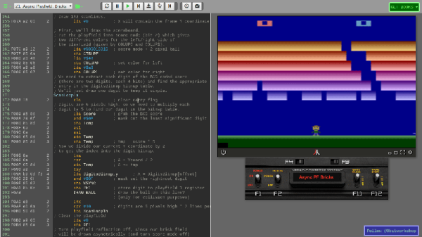
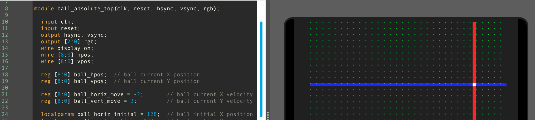
The ULX3S supports members of the Lattice ECP5 FPGA family, ranging from the 12F (12 k LUTs) to the 85F (84 k LUTs). What can you do with this much FPGA horsepower? Have a look at the long list of examples curated in the ULX3S Links repo. There, you’ll find code from retro-computing to retro-gaming, the usual LED and HDMI demos, and even Linux running on a mor1kx OpenRISC core. Maybe the most interesting links in the repo, however, are those that show how to program the FPGA with a completely open-source toolchain. Proprietary toolchains are the last link keeping some vendor’s FPGAs from wider adoption in the OSHW community, and it’s great to see people chipping away at them.
The board itself is completely open-source. In the GitHub repo, you’ll find the KiCAD 5 design files for the PCB released under an MIT-style license. Even more impressive is the advice in the README, which not only welcomes independent production of the boards, but gives some solid advice on dealing with PCBA vendors during manufacture. Our own advice is to do the right thing and offer the developers a cut if you decide to independently market this board, even though you aren’t required to by the license. If want one, but don’t want to manufacture your own, you can contact the developers using the email or gitter links at the bottom of the ULX3S page: they’re currently doing a small production run.
The Radiona Org folks have created a few videos showcasing example code. Check out how the on-board ESP-32 runs a web server that can load bitstreams into the FPGA (in this case for some retro-gaming), after the break.
Continue reading “ULX3S: An Open-Source Lattice ECP5 FPGA PCB”