Junk Box Build Helps Hams With SDR

SDRs have been a game changer for radio hobbyists, but for ham radio applications, they often need a little help. That’s especially true of SDR dongles, which don’t have a lot of selectivity in the HF bands. But they’re so darn cheap and fun to play with, what’s a ham to do?

[VK3YE] has an answer, in the form of this homebrew software-defined radio (SDR) helper. It’s got a few features that make using a dongle like the RTL-SDR on the HF bands a little easier and a bit more pleasant. Construction is dead simple and based on what was in the junk bin and includes a potentiometer for attenuating stronger signals, a high-pass filter to tamp down stronger medium-wave broadcast stations, and a series-tuned LC circuit for each of the HF bands to provide some needed selectivity. Everything is wired together ugly-style in a metal enclosure, with a little jiggering needed to isolate the variable capacitor from ground.

The last two-thirds of the video below shows the helper in use on everything from the 11-meter (CB) band down to the AM bands. This would be a great addition to any ham’s SDR toolkit.

Continue reading “Junk Box Build Helps Hams With SDR”

Creating A Bode Analyzer From A Microcontroller

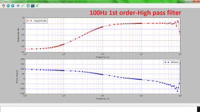
Electrical engineers will recognize the Bode plot as a plot of the frequency response of a system. It displays the frequency on the x-axis and the phase (in degrees) or magnitude (in dB) on the y-axis, making it helpful for understanding a circuit or transfer function in frequency domain analysis.

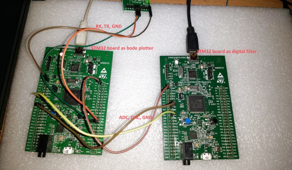
[Debraj] was able to use a STM32F407 Discovery board to build a Bode analyzer for electronic circuits. The input to the analyzer is a series of sine wave signals with linearly increasing frequency, or chirps, preferably twenty frequencies/decade to keep the frequency range reasonable.

The signals from a DAC are applied to a target filter and the outputs (frequencies obtained) are read back through an ADC. Some calculations on the result reveal how much of the signal is attenuated and its phase, resulting in a Bode plot. The filtering is done through digital signal processing from a microcontroller.

While the signals initially ran through a physical RC-filter, testing the Bode plotter with different circuits made running the signals through a digital filter easier, since it eliminates the need to solder resistors and capacitors onto protoboards. Plotting is done using Python’s matplotlib, with the magnitude and phase of the output determined analytically.

It’s a cool project that highlights some of the capabilities of microcontrollers as a substitute for a pricier vector network analyzer.

Continue reading “Creating A Bode Analyzer From A Microcontroller”

DIY Talkbox Gives You More Bounce To The Ounce

Back in the 70s, you couldn’t swing a macrame plant hanger around a record store without knocking over numerous displays of albums featuring talkboxes. They were all over 70s music, kind of like how almost every 80s song has a sax solo and/or Michael McDonald on backing vocals. Not sure you’ve heard one being used? Trust us, you definitely have and just don’t realize it.

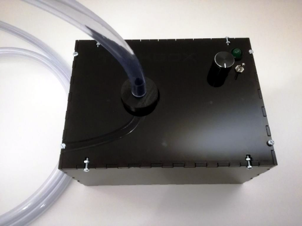
Talkboxes are essentially an amplifier and a speaker contained in a box. The speaker is the acoustic diaphragm type used in bullhorns and civil defense sirens. You run your guitar, keyboard, or electrified hurdy gurdy into the box, and instead of driving a horn, the sound travels up a clear plastic tube and into your mouth. Your mouth, fine resonant cavity that it is, becomes the final effect pedal. Any way you can manipulate it will shape the sound coming from the instrument. Flap those lips, and suddenly you’re talking like a robot. Who wouldn’t want one of these?

So they aren’t complicated, but you wouldn’t know it from the price of commercial ones. [mosivers] really digs the sound and wanted to build one, so he scoured the internet to figure out how to do so properly and shared his findings in this Instructable. The most important bit is the compression driver. The drivers that featured in the original talkboxes aren’t made anymore, but there are suitable replacements for ~$40.

The next most important part is a high-pass filter to keep really low frequencies from damaging the driver. After that it’s down to the amplifier, some passives, and the all-important tube. You could laser cut an enclosure as [mosivers] did, or be the first person in history to reuse a Danish butter cookie tin for something other than sewing supplies. Boogie on down past the break and let’s groove tonight.

Speaking of the 80s, here’s a DIY talkbox built on a Game Boy.

Continue reading “DIY Talkbox Gives You More Bounce To The Ounce”

The Right Circuit Turns Doppler Module Into A Sensor

Can you buy a working radar module for $12? As it turns out, you can. But can you make it output useful information? According to [Mathieu], the answer is also yes, but only if you ignore the datasheet circuit and build this amplification circuit for your dirt cheap Doppler module.

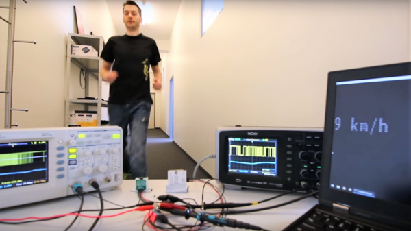
The module in question is a CDM324 24-GHz board that’s currently listing for $12 on Amazon. It’s the K-band cousin of the X-band HB100 used by [Mathieu] in a project we covered a few years back, but thanks to the shorter wavelength the module is much smaller — just an inch square. [Mathieu] discovered that the new module suffered from the same misleading amplifier circuit in the datasheet. After making some adjustments, a two-stage amp was designed and executed on a board that piggybacks on the module with a 3D-printed bracket.

Frequency output is proportional to the velocity of the detected object; the maximum speed for the sensor is only 14.5 mph (22.7 km/h), so don’t expect to be tracking anything too fast. Nevertheless, this could be a handy sensor, and it’s definitely a solid lesson in design. Still, if your tastes run more toward using this module on the 1.25-cm ham band, have a look at this HB100-based 3-cm band radio.

Continue reading “The Right Circuit Turns Doppler Module Into A Sensor”