[Jack] is famous ’round these parts for his modern reinterpretations of very early computers. He’s created a computer entirely out of logic chips, a microcontroller-powered multicore box, and even a very odd one-instruction computer. For his latest project, he’s stepped up his game and made something that’s actually fairly useful: a microcontroller-powered system with an integrated keyboard and display.
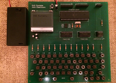
The DUO Portable, as [Jack] calls his new toy, is built around an ATMega1284P microcontroller. Also on this board is a serial EEPROM that acts as a very small drive, a 102×64 pixel graphic display, and enough tact switches to create a QWERTY keyboard.
The DUO Portable boots to a primitive operating system where files can be created, edited, and saved. The programming language for this computer is called DCPL – the DUO Portable Command Language – and can be used to create anything from a simple ‘Hello World’ program to a block-building game.
Like all of [Jack]’s homebrew computer projects, he’s written an emulator that can be run in a browser. There’s also video of [Jack] playing around with the DUO Portable available below.
Continue reading “DUO Portable: A Homebrew Computer With Keyboard And Display”