I2C Level Converter

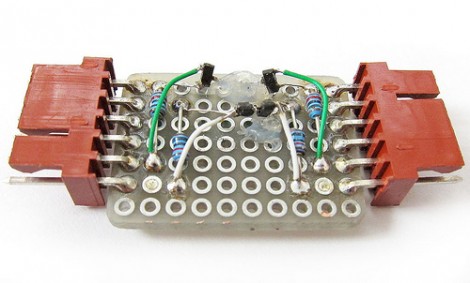
You’ve got several devices which communicate via the I2C protocol, but some of them can only operate at 3.3V while the rest are hungry for a 5V connection. What to do? [Linux-works] built this I2C level converter to solve the problem.

The circuit comes from an NXP app note (PDF) on the issue. You can take a quick peek at the suggested schematic from that document. The design uses two MOSFETS for each side of the adaptor. Perhaps a better way to explain this is that you need one for the higher voltage and one for the lower voltage on each of the two data lines for a total of four parts. This allows for both of the buses to communicate as one, while still having their own 3.3V and 5V pull-up resistors.

[Linux-works] concedes that there are chips designed to do this for you, but he was able to source the BSS138 MOSFETs locally and for about ten cents a piece. Not a bad alternative to putting in a parts order.

FT-2232 Bridges Python And I2C/SPI

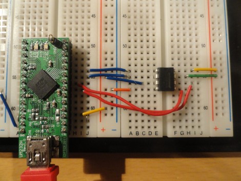
You might already have the hardware on hand to easily interface I2C and SPI devices with Python scripts on your computer. The board seen above is an FT-2232 breakout board. These chips are often used to facilitate JTAG programming via USB, but they have other features that might be useful to you as well. The chip has a Multi-Protocol Synchronous Serial Engine (MPSSE) which can speak the I2C and SPI protocols, you just need to know how to active them in your code.

[Craig] makes this easy with his MPSSE Python wrapper. Simply install his module, and you’ll be able to import all the commands you need. He demonstrates reading the data out of a 1 MB SPI flash memory chip. This could be used for a lot more, including debugging peripherals à la the Bus Pirate, or reprogramming chips to add to your projects (we’re thinking font arrays and sprites for displays, or look-up tables).

If you’re not aware, these FTDI chips were the go-to for USB support for a long time. We’ve got a guide for bit-banging using this hardware. Lately more chips have become available with USB hardware built-in. They’re quite useful and cost-effective, especially with the availability of open-source stacks like the LUFA project.

Auxiliary Display For Beat707 Works Via I2C

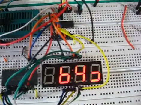
Bigtime is a simple way to create an auxiliary display for the Beat707 MIDI controller. The right half of the display shows the beat pattern that the drum machine is using, while the left half keeps track of the current measure.

Just a few components went into the extra hardware. A four-digit seven segment display is fed data from an ATtiny85. Since that microcontroller has only eight pins, a 595 shift register and CD4067 take care of translating serial data into the outputs necessary to light the display. The entire thing connects to the Beat707’s I2C bus, which means you don’t need to make hardware alterations to the original, and this leaves plenty of room for more addons.

The code package includes a Fritzing file, but for your convenience we’ve embedded a PNG of the hardware connections after the break. You’ll also find the demo video where [Guilherme] explains how this works.

Continue reading “Auxiliary Display For Beat707 Works Via I2C”

Working With I2C Port Expanders

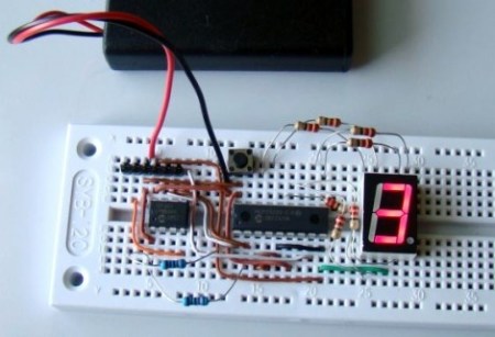
There are times when you don’t need much processing power for your project but you do need a lot of I/O pins. It often doesn’t make economic sense to choose a larger microcontroller just to get extra pins so the answer is to use a port expander chip. [Raendra] posted a guide for using one of these chips, it’s a Microchip MCP23008 chip that uses the I2C protocol for communications.

You are probably already familiar with using shift registers like the 595 series for port expansion. There can be benefits to using an I2C device instead. One of them comes when using multiple port expander chips. With cascading shift registers you must always shift in the data for the entire chain of chips. But I2C devices are individually addressable, so you only need to push data over the I2C bus for the chips that need to be changed, the others will remain unaffected. It is especially easy to use these if you already have another I2C device in your project design as the addition only requires the connection of the SDA and SCL lines. Keep them in mind for future undertakings.

I2C Arduino GPS Shield

i2c_gps_shield

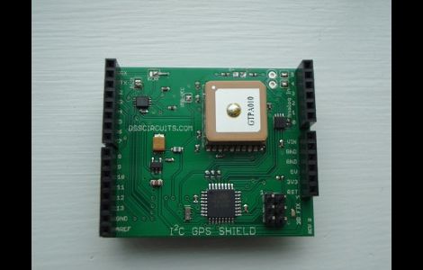
[Wayne] wrote in to share an item he just finished working on, an I2C GPS shield for the Arduino. While other GPS solutions have existed for quite some time, his caught our eye due to its feature list.

The shield removes a good bit of the hassle associated with parsing raw NMEA data from traditional GPS addons. While you have the option to communicate with the GPS module over serial in order to obtain the raw data, the use of the I2C interface makes getting the most commonly used GPS data a breeze. The GPS module itself can be set to update at anywhere from 1 to 10 Hz, and [Wayne] says that the I2C bus blows away the oft-used 9600 baud serial interface. While I2C is primarily used for receiving data, it can also be utilized to configure the GPS via its control registers, allowing for on the fly settings tweaks.

While he does sell the units pre-assembled at a competitive price, [Wayne] also provides a full schematic, making this an easy afternoon project once you have sourced the proper components.

Arduino I2C Sniffer

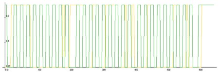
[Johngineer] found himself in need of an I2C sniffer, but didn’t have one available. Necessity is the mother of invention, so he put together this I2C sniffer sketch for Arduino. The arduino will record what is going on for a set time interval, then dump the data via serial as a .csv. You then have to plot it to see what is going on. [Johngineer] recommends Livegraph, since it is portable and easy. As you can see in the code, the time interval is adjustable, but you have the physical limitations of the RAM on the board to consider. This seems like a pretty handy piece of code stored around, effectively giving you a passable I2C sniffer in a pinch.

I2C 101

Embedded Labs has come out with a very detailed I2C 101  tutorial, that you should check out if you have any questions on the system. I2C is a short distance serial interface that only requires 2 bus lines. Keep in mind that as wires go down complexity goes up. While there are more than a few I2C devices out there in the wild, and the 2 wire system does make wiring a breeze sometimes, the information required to make use of it often seems confusing to someone who is just starting with it.

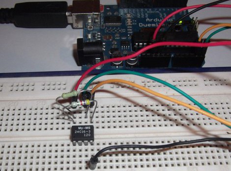
The tutorial covers basic theory, stop / start conditions, addressing, data transfer, and acknowledgment plus illustrations. A couple of specific examples are given in the form of a 24LC512 serial eeprom, and a DS1631 digital thermometer complete with code.