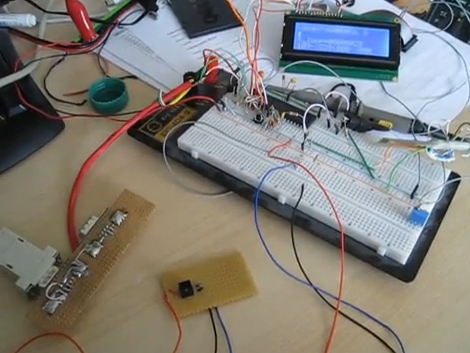
Motion Controlled Reddit Vote Sign.


A little while back I attended the largest east coast gathering of folks from the ever popular social news site, Reddit.com. Those of you familiar with Reddit already know that it is all about link aggregation. Users post links to interesting websites and material, and can then vote up or vote down content based on interest or relevance. Through the magical site algorithms original and interesting content is, as implied, aggregated up to the front page.  The whimsical nature of this big DC event lead many people to furnish signs of all types based on the culture of the site, internet memes, etc… The signs that really caught my attention were based primarily on the stylistic site layout, blowing up mail icons and other Reddit specific graphics.

The concept of using site graphics gave me the idea of being able to personally vote up or down other peoples’ signs. It was far too easy to just make a cardboard arrow, and I don’t have a color printer. I happened to have a shelved coffee table project involving orange and blue LEDs. Same colors as the arrows! Sweet. To make this project work I would have to work entirely from my project pile, there simply was no time to order anything from the internet. I managed to crank out a functional up/down voting sign in 3 days leading up to the gathering (and the morning of), here is what I did:

Continue reading “Motion Controlled Reddit Vote Sign.”

NBA Hangtime Pinball Display

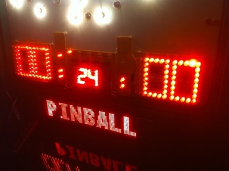
[Ed Zarick] continues work on his NBA Hangtime pinball machine with the completion of the scoreboard and backglass. You should remember this project as we already covered the layer audio he developed for the system. Now he’s proving to be a protoboard master, using point-to-point techniques to build a pair of two and a half digit LED displays for team scores, as well as a shot clock timer and other status indicators.

The lighting board that controls it all is commanded via the i2c protocol, just like the three audio modules. It uses shift registers along with MOSFETs and [Ed] has taken the time to add pin headers and sockets for board interconnects. As is true with the audio system, one Arduino Mega acts as the master on the i2c bus and you’ll notice in the video after the break that the display works in perfect harmony with the sound effects.

We can’t wait to see what he comes up with for the play field!

Continue reading “NBA Hangtime Pinball Display”

Nokia LCD, Nunchuck, And MSP430 Join Forces

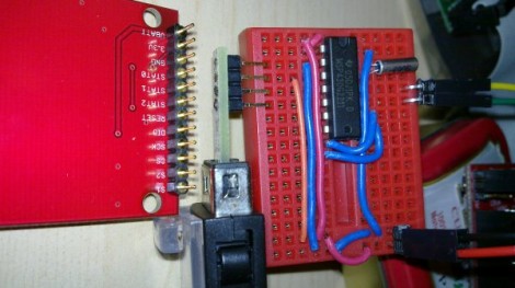
[JB’s] driving a Nokia 6100 LCD using an MSP430 with input from a Wii Nunchuck. He’s using the G2211 microprocessor that came with the Launchpad, and developing his code with MSP-GCC. As you can see in the video after the break, this works but there’s some room for improvement. That’s being said, he is bumping up against the code memory limit, with just around 500 bytes left to work with. The LCD screen is SPI and currently it’s hogging the pins that are used for the hardware i2c. Since he needs an i2c bus to talk to the nunchuck he had to go with software i2c which explains part of his program memory troubles.

We’re in no way experts on this, but it seems like he could save space (and improve the input responsiveness) by rewriting his LCD drivers in order to remap the pins. Then again, it might just be better to move up to a larger MSP430. If you’ve got some advice, make sure to share it by leaving a comment.

Continue reading “Nokia LCD, Nunchuck, And MSP430 Join Forces”

The OpenServo Project

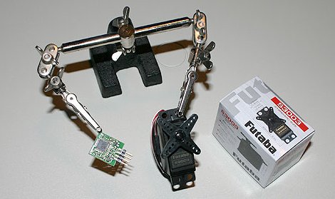
When it comes to using servos in projects, there is a definite distinction between the cheap ones and the expensive high power and precision models. The OpenServo project gives you a couple options for enhancing your servo experience. By replacing the control board with a new one based on a familiar microcontroller, a whole new set of features can be attained. For those of you out there with a need for servos like these, you can buy the pre-built replacement board (unfortunately sold out right now), or build your own from the provided schematic, BOM, and source code.

Zipitbot

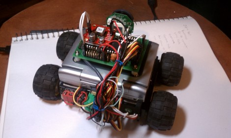
[Nulluser’s] Zipit was fine, but it couldn’t go anywhere on its own. Adding some motors and a microcontroller fixed that issue, and now he’s got a little robot called the Zipitbot. That’s a dsPIC board on top which communicates with the Zipit over an I2C bus. Four servo motors provide plenty of power to the wheels,with some extra battery packs nestled between them.

Since the Zipit is running Linux, and already has WiFi hardware, it’s not too hard to add Internet control. With this in mind there’s a webcam on the front to broadcast a video feed for use when controlling it remotely. See a couple of videos of this hack after the break.

Continue reading “Zipitbot”

Playing Piano With Optical Sensors

[Sebastian] is trying to improve the responsiveness of an electric keyboard. He was unsatisfied with the lack of adequate sensitivity to keystroke. The first step in his process was to measure how fast the quickest keystroke actually is. By setting up an LED and phototransistor and taking some measurements he found that sampling at 1 kHz would be more than adequate.

With initial testing complete he ordered some CNY70 transmissive/reflective light sensors that can be place below the keys. He measures the sensor with the ADC on an ATmega16 microcontroller. Running at 16 MHz he can sample each of the eight analog-to-digital converter channels at 1202 Hz. After doing a bunch of math he put together some lookup tables that are used to translate the ADC data into midi signals. We’ve embedded a video of one sensor controlling the midi program PianoTeq. [Sebastian] also sent us a schematic of one node in the sensor network (see it after the break).

When everything is said and done he plans to use eleven ATmega16 microcontrollers to address the 88 keys, with an additional microcontroller to act as the master using a two-wire interface for communications.

Update: [Sebastian] put up a webpage with a fairly verbose description. Reading it straight from the source really clears up a lot of questions.


Continue reading “Playing Piano With Optical Sensors”

Small And Simple FM Radio

[gpsKlaus] built this little FM radio (translated) based on the AR1010 IC. That chip is controlled via I2C by an ATtiny45 microcontroller. His tuning implementation relies on presetting 16 stations in the firmware and selecting them with the white potentiometer.

The FM chip came on a breakout board from SparkFun. Not bad at around $15 as it includes the crystal, some caps and a few resistors, and you don’t have to try and solder to the fine pitched pads on that minuscule package. We’re a little unsure of the features included in the part as the datasheet is lacking in detail and the reference datasheet that SparkFun includes in the description is obviously for a much more full-featured chip. Still, this would be a fun thing to play around with if you’ve grown tired of blinking LEDs.

If you don’t want to let an integrated circuit do all the heavy lifting try this post for a guide on building your own radio tuner.