Line Following Robot Without The Lines

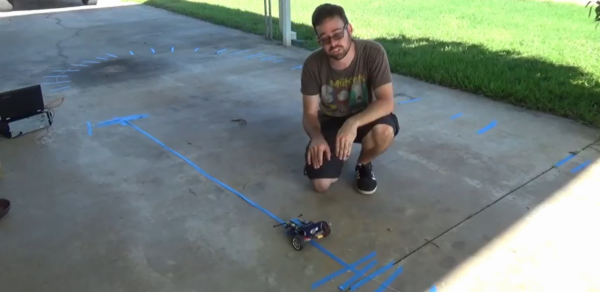
Line-following robots are a great intro to robotics in general, since the materials and skills needed to build a good one aren’t too advanced. It turns out that line-following robots are more than just a learning tool, too. They’re pretty useful in industry, but most of them don’t follow visible marked lines. Some, like this inductive guided robot from [Randall] make use of wires to determine their paths.

Some of the benefits of inductive guidance over physical lines are that the wires can be hidden in floors, so if something like an automated forklift is using them at a warehouse there will be less trip hazard and less maintenance of the guides. They also support multiple paths, so no complicated track switching has to take place. [Randall]’s robot is a small demonstration of a larger system he built as a technician for an autonomous guided vehicle system. His video goes into the details of how they work, more of their advantages and disadvantages, and a few other things.

While inductive guided robots have been used for decades now, they’re starting to be replaced by robots with local positioning systems and computer vision. We’ve recently seen robots that are built to utilize these forms of navigation as well.

Continue reading “Line Following Robot Without The Lines”

Putting A Poor Man’s Vector Analyzer Through Its Paces

If anything about electronics approaches the level of black magic, it’s antenna theory. Entire books dedicated to the subject often merely scratch the surface, and unless you’re a pro with all the expensive test gear needed to visualize what’s happening, the chances are pretty good that your antenna game is more practical than theoretical. Not that there’s anything wrong with that — hams and other RF enthusiasts have been getting by with antennas that work without really understanding why for generations.

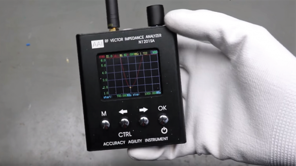
But we’re living in the future, and the tools to properly analyze antenna designs are actually now within the means of almost everyone. [Andreas Spiess] recently reviewed one such instrument, the N1201SA vector impedance analyzer, available from the usual overseas sources for less than $150. [Andreas]’s review does not seem to be sponsored, so it seems like we’re getting his unvarnished opinion; spoiler alert, he loves it. And with good reason; while not a full vector network analyzer (VNA) that will blow a multi-thousand dollar hole in your wallet, this instrument looks like an incredible addition to your test suite. The tested unit works from 137 MHz to 2.4 GHz, so it covers the VHF and UHF ham bands as well as LoRa, WiFi, cell, ISM, and more. But of course, [Andreas] doesn’t just review the unit, he also gives us a healthy dose of theory in his approachable style.

[The guy with the Swiss accent] has been doing a lot of great work these days, covering everything from how not to forget your chores to reverse engineering an IoT Geiger counter. Check out his channel — almost everything he does is worth a watch.

Continue reading “Putting A Poor Man’s Vector Analyzer Through Its Paces”

Design A Coil For A Specific Inductance

YouTuber [RimstarOrg], AKA Hackaday’s own [Steven Dufresne], shows how to make a DIY inductor for a specific inductance. This is obviously a great skill to learn as sometimes your design may call for a very accurate inductance that may be otherwise hard to find.

Making your own inductor may seem daunting. You will have to answer a few questions such as: “what type of core will I use?”, “how many turns does my coil need?”, or “how do I calculate these parameters to create the specific inductance I desire?”. [RimstarOrg] goes through all of this, and even has a handy inductance calculator on his website to make it easier for you. He also provides all the formulae needed to calculate the inductance in the video below.

Using a DIY AM Radio receiver, he demonstrates in a visual way how to tune an AM Radio with a wiper on his home-built coil. Changing the inductance with a wiper changes the frequency of the radio: this is a variable inductor,

This video is great for understanding the foundations of inductors. While you may just go to a supplier and buy yours, it’s always great to know how to build your own when you can’t find a supplier, or just can’t wait.

Continue reading “Design A Coil For A Specific Inductance”

Yet Another Inductance Measuring Scheme

How do you measure the value of an unknown inductor? If you have an LCR bridge or meter, you are probably going to use that. If not, there are many different techniques you can use. All of them rely on the same thing my Algebra teacher Mr. Harder used to say back in the 1970’s: you have to use what you know to get what you don’t know.

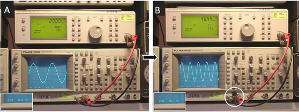
[Ronald Dekker] must think the same way. He took a 50-ohm signal generator and a scope. He puts the signal output to about 20kHz and adjusts for 1V peak-to-peak on the scope. Then he puts the unknown inductor across the signal and adjusts the frequency (and only the frequency) for an output of 1/2 volt peak-to-peak.

Continue reading “Yet Another Inductance Measuring Scheme”

The Beginnings Of An LCR Meter

LCR Meter

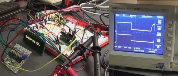
The inductor is an often forgotten passive electrical elements used to design analog circuitry. [Charles’s] latest proof of concept demonstrates how to measure inductance with an oscilloscope, with the hopes of making a PIC based LCR meter.

It is not that often one needs to measure inductance, but inductors are used in switching regulators, motor circuits, wireless designs, analog audio circuitry, and many other types of projects. The principles of measuring inductance can be used to test inductors that you have made yourself, and you can even use this knowledge to measure capacitance.

[Charles] originally saw a great guide on how to measure impedance by [Alan], and decided to run with the idea. Why spend over $200 on an LCR meter when you can just build one? That’s the spirit! Be sure to watch [Alan’s] and [Charles’s] videos after the break. What kind of test equipment have you built in order to save money?

Continue reading “The Beginnings Of An LCR Meter”

Making A Power Inductor Checker

inductor-checker-for-oscilloscope

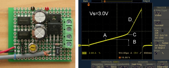
Back to the basics: there are three kinds of passive electronic components: Inductors, Capacitors and Resistors. An inductor can be easily built and many types of core and bobbin kits are available. However, characterizing one hypothetical coil you just made is quite tricky as its inductance will depend on the measurement frequency and DC bias current. That’s why [ChaN] designed the circuit shown above.

As you may guess, RF enthusiasts are more interested in the inductance vs frequency curve while power circuit designers prefer inductance vs load current (for a given frequency). The basic principle behind the circuit shown above is to load an inductor for repetitive short periods and visualizing the current curve with an oscilloscope connected to a sense resistor. When loading the inductor, the current curve will be composed of two consecutive slopes as at a given moment the coil’s core will be saturated. Measuring the slope coefficient then allows us to compute the corresponding inductance.

[Via Dangerous Prototypes]

Measuring SMD Parts With A Home Brew Version Of Smart Tweezers

SMD parts are great; they allow you to pack more parts on a board, do away with drilling dozens of PCBs, and when done correctly can produce a factory-quality board made in a home lab. There’s one problem with SMD parts; troubleshooting and measuring them. The ideal solution would be something akin to the Smart Tweezers we’ve seen before, but this fabulous tool costs three hundred bones. [Kai] came up with a much cheaper solution: home brew smart tweezers that can be built for a tenth of the cost as the professional model.

What [Kai] built is an LCR meter, basically a tool that measures inductance, capacitance, and resistance in a very, very small form factor. The technique of measuring a part’s properties involves feeding a set frequency into the device and measuring the phase, voltage and current coming out. It’s all wonderfully explained by [Dave] over at EEVblog in one of his earlier videos.

The hardware [Kai] is using includes an LCD display from a Nokia phone, an MSP430-based microcontroller, a very tiny opamp near the tip of one of the points of the tweezer, and a programmable gain amplifier used to measure the components. In testing, [Kai] can measure very low-value components with a +/- 2% accuracy, and larger, more realistic components with +/- 0.25% accuracy. An awesome accomplishment, and much better than the common Chinese meters that can’t measure in the nH/pF/mΩ range.

[Kai] hasn’t gotten his pair of smart tweezers working yet – he still needs to get the circuit up and running and write some software. We’ll keep our readers apprised of [Kai]’s progress, though, and gently convince him to work with Seeed Studio or someone similar to get his version of Smart Tweezers onto maker’s workbenches the world over.