Chances are pretty good you’ve had a glowing probe clipped to your fingertip or earlobe in some clinic or doctor’s office. If you have, then you’re familiar with pulse oximetry, a cheap and non-invasive test that’s intended to measure how much oxygen your blood is carrying, with the bonus of an accurate count of your pulse rate. You can run down to the local drug store or big box and get a fingertip pulse oximeter for about $25USD, but if you want to learn more about photoplethysmography (PPG), [Rajendra Bhatt]’s open-source pulse oximeter might be a better choice.
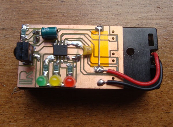
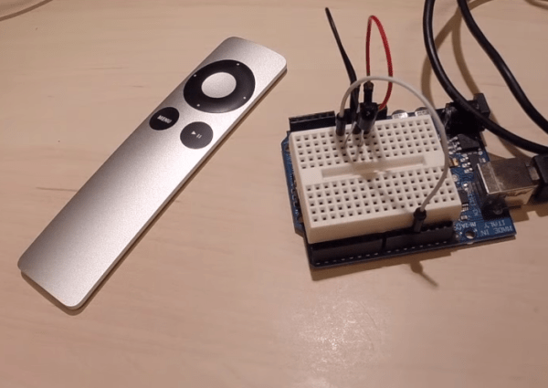
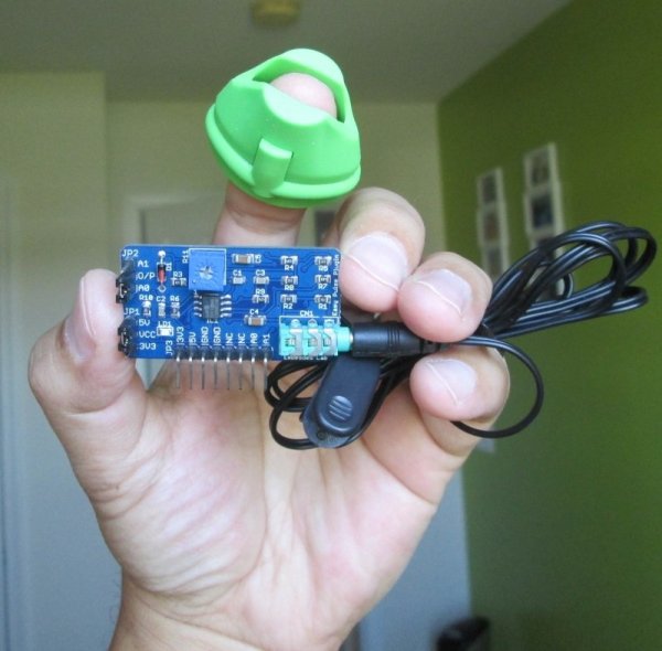
PPG is based on the fact that oxygenated and deoxygenated hemoglobin have different optical characteristics. A simple probe with an LED floods your fingertip with IR light, and a photodiode reads the amount of light reflected by the hemoglobin. [Rajendra]’s Easy Pulse Plugin receives and amplifies the signal from the probe and sends it to a header, suitable for Arduino consumption. What you do with the signal from there is up to you – light an LED in time with your heartbeat, plot oxygen saturation as a function of time, or drive a display to show the current pulse and saturation.
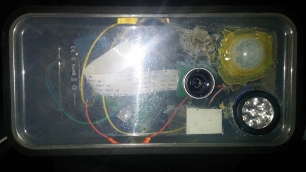
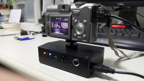
We’ve seen some pretty slick DIY pulse oximeters before, and some with a decidedly home-brew feel, but this seems like a good balance between sophisticated design and open source hackability. And don’t forget that IR LEDs can be used for other non-invasive diagnostics too.