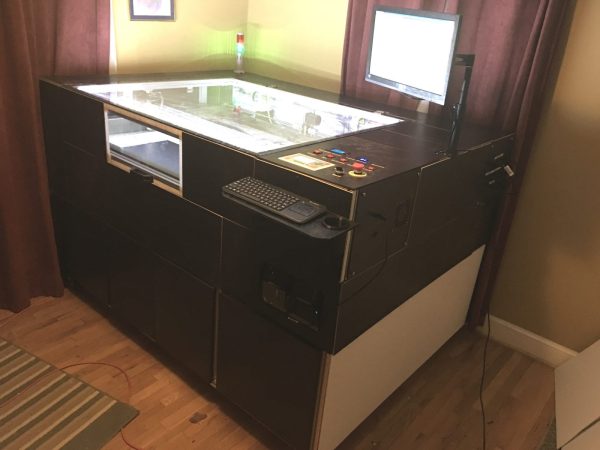
Nothing says swinging 21st-century bachelor pad better than a laser cutter. To really make a statement, you want a custom-built, 100 Watt, 1200mm x 900mm laser cutter.
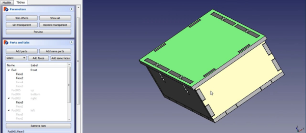
The bachelor in question, [drandolph], rightly points out that a $6,000 build that takes up a significant fraction of the floor space in one’s apartment is better attempted without the benefit of spousal oversight. Still, what spouse couldn’t love the finished product? With a custom aluminum extrusion frame (which barely made the trip from China intact) it’s a sturdy affair, and who could deny the appeal of the soft glow of an LED-illuminated work chamber? A custom exhaust system with sound-deadening, a water chiller for laser cooling, an Arduino-controlled status beacon – there’s even a 3-D printed beer holder on the control panel! And think of all the goodies that will come off the enormous bed of this thing. Note to self: make sure wife sees this post.
There are cheaper and smaller laser cutters, but what’s the point if you have the freedom to go big?
[via r/DIY]
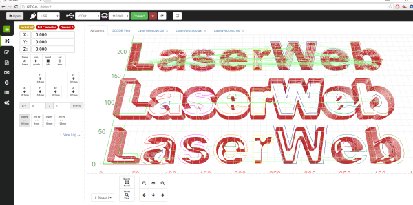
 LaserWeb3 supports different controllers and the machines they might be connected to – whether they are home-made systems, CNC frames equipped with laser diode emitters (such as retrofitted 3D printers), or one of those affordable blue-box 40W Chinese lasers with the proprietary controller replaced by something like a