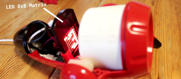
We remember going to grandfather’s garage. There he would be, his tobacco pipe clenched between his teeth, wisps of smoke trailing into the air around him as he focused, bent over another of his creations. Inside of a simple glass bottle was something impossible. Carefully, ever so carefully, he would use his custom tools to twist wire. He would carefully place each lead. Eventually when the time was right he would solder. Finally he’d place it on the shelf next to the others, an LED matrix in a bottle.
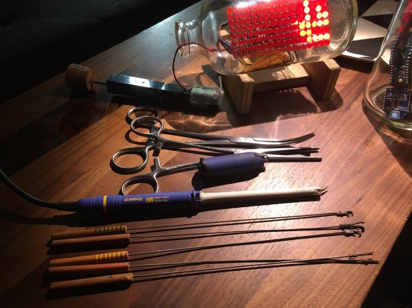
 Well, maybe not, but [Mariko Kosaka]’s father [Kimio Kosaka] has done it. In order to build the matrix, he needed tools that could reach inside the mouth of the bottle without taking up too much space to allow for precise movement. To do this he bent, brazed, twisted, and filed piano wire into tools that are quite beautiful by themselves. These were used to carefully bend and position the LEDs, wires, and other components inside the bottle.
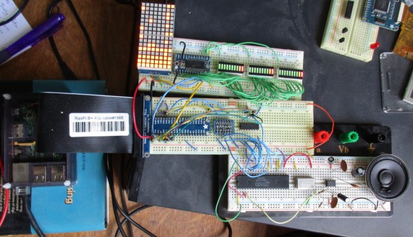
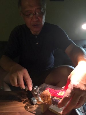
Once the part was ready, he used a modified Hakko soldering iron to do the final combination. We wonder if he even had to be careful to solder quickly so as not to build up a residue on the inside of the bottle? The electronics are all contained inside the bottle. One of the bottles contained another impressive creation of his: an entire Arduino with only wire, dubbed the Arduino Skeleton. Batteries are attached to the cork so when the power runs low it can be removed and replaced without disturbing the creation.
It’s a ridiculous labor of love, and naturally, we love it. There’s a video of it in operation as well as one with him showing how it was done which is visible after the break. He showed them off at the Tokyo Maker Faire where they were surely a hit.
Continue reading “Electronic Message In A Bottle” →