A logic analyzer records bus communications between two chips. If you’ve ever had a problem getting two chips to talk, or wanted to reverse engineer a protocol, a logic analyzer is the tool you need to spy on the bus.
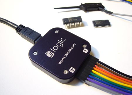
The Logic is a USB logic analyzer with eight channels and sampling rates up to 24MHz. Among hobby-level logic analyzers, the Logic has a good mix of features and decent sampling rates. We’ve been following Joe Garrison’s work on the Logic for a long time. If you’ve ever considered bringing a product to market, you can learn a lot from Joe’s blog that documents his development process.
When it debuted, the Logic was so popular that it was hard to buy one. It’s now widely available, and Saleae gave us one to try. Read our review below.