It’s awesome when you can tag-team with your dad to fix stuff around the house. [Ilias Giechaskiel], with help from his dad, did a complete refurbishing of a broken bathroom weighing scale, but not before trying to fix it first. The voltage regulator looked bust. Powering the rest of the circuit directly didn’t seem to work, and none of the passives looked suspect. Most of the chips had their markings scratched off and the COB obviously couldn’t be replaced anyway.
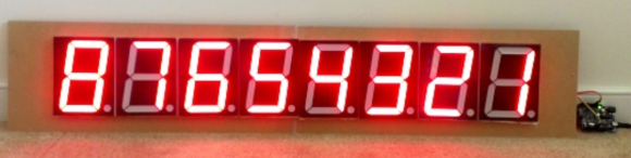
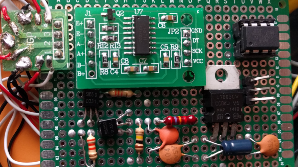
Instead of reverse engineering the LCD display, they decided to retain just the sensor and the switches, and replace everything else. The ATtiny85 seemed to have enough IO pins to do the job. But the strain-gauge based load cell, connected in a bridge configuration, did not have a signal span large enough to be measured using the 10 bit ADC on the ATtiny. Instead, they decided to use the HX711 (PDF) – a 24 bit ADC with selectable gain, specifically meant for use in weighing scales. Using a library written for the HX711 allowed interfacing it to the Arduino easy. The display was built using a 4 digit 7 segment display driven by the MAX7219. A slightly modified LEDcontrol library made it easy to hook up the display to the ATtiny. The circuit was assembled on a prototyping board so that it could be plugged in to another Arduino for programming.
Since they were running out of pins, they had to pull out a trick to use a single pin from the ATtiny to act as clock for the display driver and the ADC chip. Implementing the power-on and auto-off feature needed another interesting analog circuit block. Dad did the assembly of the circuit on a prototype board. In hindsight, the lack of IO pins on the ATtiny limited the features they could implement, so the duo are planning to put in an Arduino Nano to improve the hack. If you’re ever stuck with a broken scale, he’s made the schematic (PNG) and code available for use.

 [Neven Boyanov] says there’s nothing special about