Rise And Shine With This Japanese-Inspired Clock

On the Hackaday.io page for his gorgeous “Sunrise Alarm Clock”, [The Big One] is quick to point out that his design is only inspired by Japanese lanterns, and does not use authentic materials or traditional woodworking techniques. Perhaps that’s an important fact to some, but we’ll just say that the materials used seem far less important when the end result looks this good.

Unfortunately [The Big One] hasn’t provided any interior shots of his clock, as it sounds like the aesthetics of the internal wiring isn’t quite up to the standard set by the outside of it. But he has provided a concise parts list, a wiring diagram, and source code, so we’ve got a pretty good idea of what’s under the hood.

The clock is powered by the uBBB 32u4, an ATMega32u4 development board that [The Big One] developed in conjunction with [Warren Janssens]. It uses the popular MAX7219 LED matrix for the display, and a DS3231 RTC module to help keep the time. There’s also a DFPlayer Mini module onboard that allows him to play whatever sound effects or music he wants when the alarm goes off.

Of course the star of the show is the LED strips which illuminate the shōji-style column. These have apparently been wrapped around a coffee can of all things, which not only serves as a convenient way of holding the strips, but [The Big One] says actually makes the speaker sound a bit better. Hey, whatever works.

This isn’t the first “lantern” clock to grace these pages, but compared to the high-tech presentation of previous projects, we can’t help but be impressed by the grace and elegance of this wooden masterpiece.

Resistance Is Futile, You Want This LED Cube

We’re suckers for a good desk toy here at Hackaday, so this 2019 Hackaday Prize entry from [Jack Flynn] certainly caught our eye. The idea is that by using professionally manufactured dual layer PCBs and only surface mount components, you can create a cube that has an LED matrix on each face and all of the electronics hidden within. We’re not entirely sure if there’s any practical application for such a device, but we know we’d certainly like to have one blinking madly away on our shelf regardless.

Before having any of the PCBs manufactured, [Jack] is putting a considerable amount of thought into the design so he doesn’t end up painting himself info a corner (which is of course eight times as bad when you’re building a cube). By importing the PCB files into OnShape, he’s able to “assemble” a virtual representation of the final product to better understand how everything will fit together. He wants to limit the amount of times the cube will need to be pulled apart, so everything from how it will sit in its 3D printed cradle to the placement of breakaway tabs that ensure the internal power switch is accessible are being carefully planned out.

The current design puts the “brains” on the bottom board, with every other panel holding a daisy-chained MAX7219 to drive its own individual 64 LED matrix. Initially the dimensions of the ATmega328p powered cube will be 42 x 42 x 42 mm, with a total of 384 LEDs. Ultimately, [Jack] hopes the modular nature of the design could allow the size of the cube to be increased, or perhaps even take on a different shape entirely.

Generally the LED cubes we see are of the more wiry variety, so it’s particularly interesting when they take on solid forms like this one. Given the nearly universal popularity of blinking LED gadgets, we think this particular project is well positioned to make the leap from one-off hack to a commercial product.

Continue reading “Resistance Is Futile, You Want This LED Cube”

Raspberry Pi Counts Down To The Last Bitcoin

Even though it might appear to be pretend Internet money, by design, there are a finite number of Bitcoins available. In the same way that the limited amount of gold on the planet and the effort required to extract it from the ground keeps prices high, the scarcity of Bitcoin is intended to make sure it remains valuable. As of right now, over 80% of all the Bitcoins that will ever exist have already been put into circulation. That sounds like a lot, but it’s expected to take another 100+ years to free up the remaining ones, so we’ve still got a way to go.

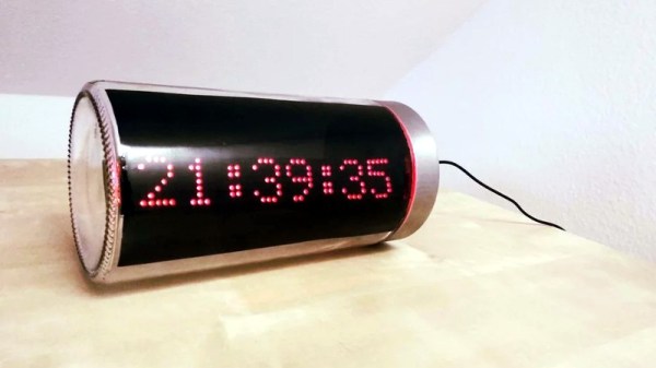
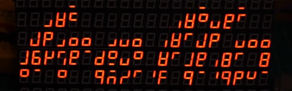
Even though his device will probably no longer exist when the final Bitcoin hits the pool, [Jonty] has built a ticker that will count down as the final coins get mined from the digital ground. The countdown function is of course a bit tongue-in-cheek, but the gadget also shows slightly more pertinent information such as the current Bitcoin value, so you can always remember what a huge mistake it was not to invest while they were still worth pennies.

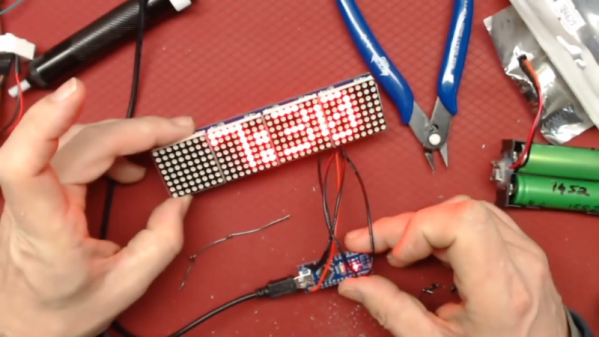
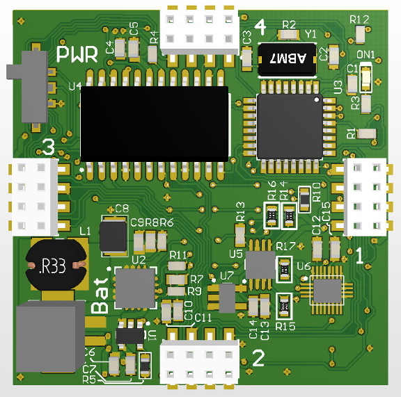
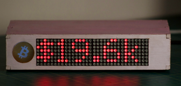
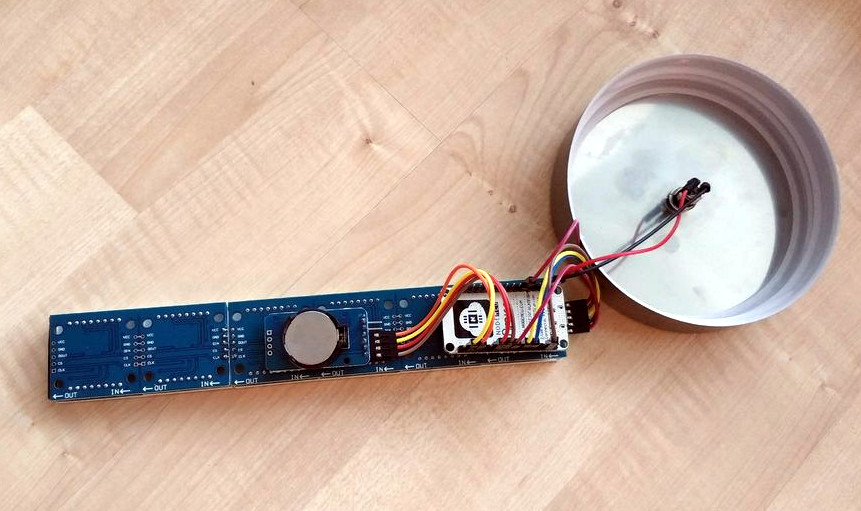
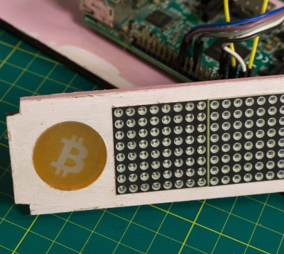
On the hardware side, this is a pretty simple project. The enclosure is laser cut 5 mm MDF, and it holds a Raspberry Pi 3, a MAX7219 32×8 LED dot matrix display, and a 10 mm white LED with accompanying resistor. The white LED is placed behind an acrylic diffuser to give the Bitcoin logo on the side of the display a soft pleasing glow when the device is powered up. There are no buttons or other controls on the ticker, once the software has been configured it just gets plugged in and away it goes.

As for the software, it takes the form of a Python script [Jonty] has created which uses Requests and Beautiful Soup to scrape the relevant data from bitcoinblockhalf.com. The script supports pulling any of the 19 variables listed on the site and displaying it on the LED matrix, which range from the truly nerdy stats like daily block generation to legitimately useful data points that anyone with some Bitcoin in their digital wallets might like to have ticking away on their desks.

The first decade of Bitcoin has been a pretty wild ride, not only monetarily, but in the wide array of hardware now involved in cryptocurrency mining and trading. From Bitcoin traffic lights to custom-made mining rigs that are today more useful as space heaters, it takes a lot of hardware to support these virtual coins.

Continue reading “Raspberry Pi Counts Down To The Last Bitcoin”

ESP8266 Clock Puts Time In A Jar

Ironically, with the wide availability of modular electronic components today, the hardest part of constructing your latest gadget might just end up being able to find a decent looking enclosure for it. Project boxes will only get you so far, and let’s be honest, they aren’t exactly the most attractive things in the world. But if you’re willing to think outside the box (get it?) there are some unconventional options out there that might fit the bill.

Take for example this ESP8266 clock by [ZaNgAbY] that’s housed in a glass pasta jar. With the addition of some window tint film for the LED display to shine through, the final result could nearly pass as modern art. Even if you don’t need an extra clock around the house, this same general principle could be used to create a slick-looking ticker for all sorts of information, from the weather to server uptime with just some adjustments to the code.

Inside the jar there’s six 8×8 MAX7219 LED matrix modules tacked together to create one long strip, with a NodeMCU board stuck to the back with double-sided tape. There’s also a DS3231 RTC module so the clock can keep halfway decent time, but depending on how aggressively you are willing to pull down the current time from NTP, that may or may not be required. A simple barrel jack is popped through the metal lid of the jar for power, and represents the only physical connection the internals have to the outside world.

For the next iteration [ZaNgAbY] is thinking of adding a temperature and humidity sensor, and a light sensor that can dim the LED display depending on the ambient light. While the environmental sensors will have to go on the outside of the lid if there’s any hope of pulling useful readings from them, the clear glass will allow him to keep the light sensor internal to the clock.

Believe it or not, this isn’t the first time we’ve seen somebody give their electronics the pickle treatment. We’ve previously played host to a server that “preserves” files in a Mason jar, as well as a gorgeous display of an iPod under glass.

Continue reading “ESP8266 Clock Puts Time In A Jar”

An 840 Segment Display

A while back, [limpfish] bought a few four-digit seven-segment displays from a seller on eBay. A month or two later, thirty displays ended up in [limpfish]’s mailbox. Instead of using the one or two displays he thought he ordered, [limpfish] decided to do something very cool with these bits of seven-segment displays. He’s controlling all of them at once.

[limpfish]’s usual method of controlling a lot of LEDs is the MAX7219 LED driver. This chip can easily — and cheaply — control eight common cathode seven segment displays. There’s a problem with this plan, though: the LEDs received from eBay are common anode. That’s actually not a problem, because with a little effort and even more thinking [limpfish] got these displays to work with the MAX7219 driver chip.

With chips in hand, [limpfish] designed a small breakout board for the MAX7219 and two common anode 4×7 segment displays. These displays can be daisy chained, and connecting them all together results in a very weird but very cool visualization.

[limpfish] is treating this display as a bitmap display, which means it’s demo time. You can check out a 1337 01d skool demo playing on this 840-segment display in the video below.

Continue reading “An 840 Segment Display”

Father And Son Fix A Scale

It’s awesome when you can tag-team with your dad to fix stuff around the house. [Ilias Giechaskiel], with help from his dad, did a complete refurbishing of a broken bathroom weighing scale, but not before trying to fix it first. The voltage regulator looked bust. Powering the rest of the circuit directly didn’t seem to work, and none of the passives looked suspect. Most of the chips had their markings scratched off and the COB obviously couldn’t be replaced anyway.

Instead of reverse engineering the LCD display, they decided to retain just the sensor and the switches, and replace everything else. The ATtiny85 seemed to have enough IO pins to do the job. But the strain-gauge based load cell, connected in a bridge configuration, did not have a signal span large enough to be measured using the 10 bit ADC on the ATtiny. Instead, they decided to use the HX711 (PDF) – a 24 bit ADC with selectable gain, specifically meant for use in weighing scales. Using a library written for the HX711 allowed interfacing it to the Arduino easy. The display was built using a 4 digit 7 segment display driven by the MAX7219. A slightly modified LEDcontrol library made it easy to hook up the display to the ATtiny. The circuit was assembled on a prototyping board so that it could be plugged in to another Arduino for programming.

Since they were running out of pins, they had to pull out a trick to use a single pin from the ATtiny to act as clock for the display driver and the ADC chip. Implementing the power-on and auto-off feature needed another interesting analog circuit block. Dad did the assembly of the circuit on a prototype board. In hindsight, the lack of IO pins on the ATtiny limited the features they could implement, so the duo are planning to put in an Arduino Nano to improve the hack. If you’re ever stuck with a broken scale, he’s made the schematic (PNG) and code available for use.

Arduino Pumpkin

8×8 LED Arrays Make For One Creepy Animated Pumpkin

[Michal Janyst] wrote in to tell us about a little project he made for his nephew in preparation for Halloween – a jack-o-lantern with facial expressions.

Pumpkin Eyes uses two MAX7219 LED arrays, an Arduino nano, and a USB power supply. Yeah, it’s pretty simple — but after watching the video you’ll probably want to make one too. It’s just so cute! Or creepy. We can’t decide. He’s also thrown up the code on GitHub for those interested.

Of course, if you want a bit more of an advanced project you could make a Tetris jack-o-lantern, featuring a whopping 8×16 array of LEDs embedded directly into the pumpkin… or if you’re a Halloween purist and believe electronics have no place in a pumpkin, the least you could do is make your jack-o-lantern breath fire.

Continue reading “8×8 LED Arrays Make For One Creepy Animated Pumpkin”