Meter Clock Using The TI Launchpad

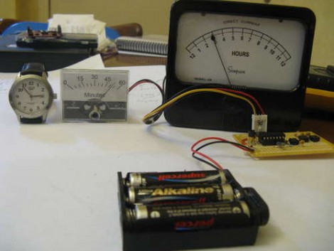
Here’s an analog meter clock using an MSP430G2211 microcontroller. [Doug Paradis] chose this processor because it is the lesser of the two that come with the TI Launchpad. The parts count is fairly low too; a clock crystal, two analog meters, a few buttons, and a voltage regulator.

He’s done a nice job putting this together. We challenge you to give this a try yourself and build on [Doug’s] features. We really liked the calibration subroutine in [Alan’s] multi meter clock. It would be fun to implement that functionality and store the calibration code in the MSP’s flash memory. You can use our ported garage door opener code if you need an example of how to store data in flash.

Whole House Current Monitoring

[youtube=http://www.youtube.com/watch?v=HlRBrTTLQFU]

[Debraj Deb] put together a current monitoring device that interfaces with the circuit box at his house. The system is controlled by a PIC 18F4520 and uses an LM358 Op-Amp to rectify the AC signal, as well as an MCP6S21 for range adjustments for detecting both high or low current loads. The data displayed on a character LCD includes average, RMS, and peak current. For now the data is saved to an EEPROM and can be dumped using a serial connection but [Debraj] plans to add a GSM modem so he can send energy use data to his cell phone.

[Thanks Ganesh]

Volt Meter Clock

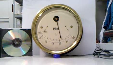
The Volt meter clock continues our recent slew of interesting clock projects. Though considerably easier to read than the resistor clock, it is in the same frame of mind. Set up to look like the face of an analog volt meter, it almost looks like something official or scientific. Since [Jon] couldn’t simply drop a clock mechanism in, he used a PIC microcontroller. The circuit is pretty simple, but he deserves some credit just for the unique layout.

C-clamp Current Monitoring

[Hydronic] did some tests to make his own current sensor using a c-clamp wrapped with wire. He tried several different cores including an aluminum carabiner, the C-clamp, and what he calls a u-lock (removable chain link). There is some success here that could be improved with cleaner winding and by adjusting readings based on the length of wire used in the wrapping.

This did make us perk up a bit right off the bat. Reader [Mure], who tipped us off about this, suggested that this could be used to make your own Kill-a-Watt without including it in the circuit. We made the jump to house monitoring. We’d love to have a data tracker for our home circuits to curb wasteful energy use. Perhaps we’ll try to make our own sensors and produce a diy Cent-a-Meter.

Kill A Watt Teardown

killawatt

Come on, folks. If we keep tearing apart everything that’s handed to us, we’ll never get nice things. SparkFun got their mitts on two Kill A Watts and proceeded to plug them into everything and then dismantled them to see how they work. The Kill A Watt keeps track of how much power is used over time. The largest load they found was their soda machine using 500W (should probably add a motion sensor to that). They plugged a meter on either side of a UPS and found out that it uses 5W just to charge. On the inside of the meter, there isn’t anything too substantial. One unlabeled IC runs the whole show.

LED Battery Level Indicator

[Kc7fys] came up with a this simple battery level indicator. It uses a single LED to display a battery’s voltage; if the voltage exceeds 12V, it glows green. If it is below 11V, the LED glows red. Anything in between generates an orange glow. The meter is built around an LM358 chip per this schematic, but his actual build looks pretty sloppy because of the dead-bug assembly (check out NASA’s pretty version). Nonetheless, it works, so clean it up and build one if you want to put it (or your batteries) to the test.