Prototyping A Modular LED Matrix

led-matrix-modular-prototype

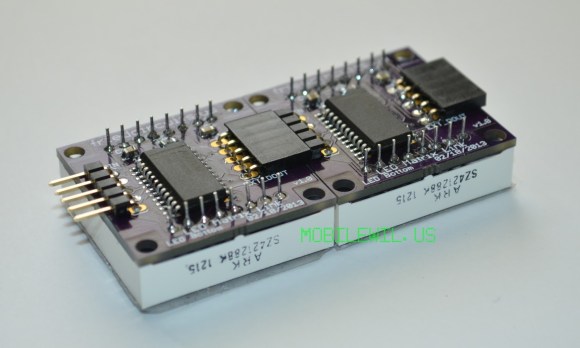
[Will] was toying with the idea of creating a scrolling LED marquee to display messages as his wedding in May. But you’ve got to crawl before you can walk so he decided to see what he could do with the MAX7219 LED driver chips. They do come in a DIP package, but the 24-pin 0.1″ pitch chip will end up being larger than the 8×8 LED modules he wanted to use. So he opted to go with a surface mount part and spun a PCB which makes the LEDs modular.

These drivers are great when you’re dealing with a lot of LEDs (like the motorcycle helmet of many blinking colors). Since they use SPI for communications it’s possible to chain the chips with a minimum of connections. [Will] designed his board to have a male header on one side and a female socket on the other. Not only does it make aligning and connecting each block simple, but it allows you to change your mind at any time about  which microcontroller to use to command them. For his first set of tests he plugged the male header into a breadboard and drove it with an Arduino. We hope to hear back from him with an update when gets the final device assembled in time for the big day.

Adding A Bluetooth Terminal To Your Router

bluetooth-router-terminal

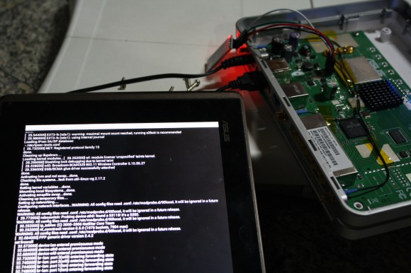
This image shows an Android tablet monitoring the terminal of a router via Bluetooth. It makes it a snap to tweak your router from a multitude of devices as long as you’re within range (usually BT works up to about 30 feet or so). The only part that [Yohanes] needed to pull off the hack was a Bluetooth module which he picked up for a few dollars.

All routers will have serial connections somewhere on the board. His model (Asus RT-N16) even had the GND, RX, TX, and VCC pads labeled. He soldered a SIL pin socket to the port which accepts the pin header from the Bluetooth module. Before plugging that in he had to issue a few commands to the device to get it using the same baud rate and settings as the router’s serial port. With that taken care of he can now wirelessly monitor and control the device via the serial terminal.

The one issue which he did encounter is that the module is slower to boot than the router. This means that at power-up you will not see anything on the terminal until the router has already started to load the Linux kernel. If you don’t plan on doing any bootloader hacks this shouldn’t make any difference.

Kilonode: How To Test A Huge Xbee Mesh Network

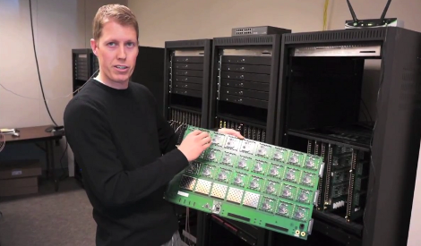
So let’s say that you’re a developer on the Xbee team. You need to test the extremes of what the RF radio modules can do when in a large network. But in addition to numerous nodes, you also need to test the effects of distance on the radios. Since it’s not reasonable to distribute hundreds of the devices (each with their own power source) throughout town, you build a test setup like the 1 kilonode Xbee rig which the project manager, [Jared Hofhiens] is showing off.

He’s holding one blade from the rack-mounted system. Each of those squares is an Xbee module, there’s 32 etched onto the board. On the edge furthest from him there are a set of connectors which mate with the rack connectors, hooking the blade up to a set of terminal servers. These servers allow developers to ssh into individual modules. On the near side of the blade there’s a set of attenuation adjustment circuits. They allow adjustments of 0-40 dB of attenuation in 10 dB increments to adjust how strong the RF signals are, simulating distance between modules.

Thirty-two of these cards are mounted in the three racks seen above to make up the 1024 module node. We really appreciate this look behind the scenes and think you’ll enjoy the video tour after the break. If it leaves you wanting more check out how one company builds cloud storage. Continue reading “Kilonode: How To Test A Huge Xbee Mesh Network”

DIY Breadboard Modules For Easy Prototyping

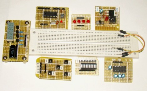
[Rajendra] got tired of building the same basic circuits time and again on the breadboard. He decided to build some simple, modular circuits on protoboard and make them easy to interface with the breadboard. As you can see, he ended up with seven modules that make prototyping faster and easier.

At first glance some might not seem all that beneficial. For instance, making a board for an 18-pin PIC microcontroller into a single-in-line form factor would seem like you’re actually wasting breadboard space when compared to the DIL package of the chip. But consider that the oscillator and its capacitors, reset button, and programming header are also on the breakout board and will not have to be built in place. There are also several I/O boards, one with five buttons, another with an LED bar graph, and a set of LEDs with a SIL resistor package on-board. These modules can be plugged into a breadboard and wired up with jumper wires, or connected directly to the same rows as the microcontroller module.

Modular Synthesizer Is Rack-mounted And Reconfigurable

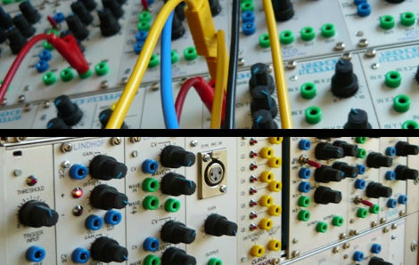
[Dirk] let us know about this fantastic music synthesis experimentation setup (translated). Turn your computer speakers off (to avoid the auto-playing music when every page loads) and dig into the wealth of information in this repository. Literally dozens of modules have been built and superbly mounted on a rack system. Each can be connected with other modules into an incredible number of different setups using patch wires that terminate with banana plugs.

The module enclosures themselves are made to fit in a standard 19″ rack. The front bezels were designed in CAD, with the rest of the housing made mostly of aluminum. Since each module tends to be quite small several are ganged into one rack skeleton to save space. You can see in the images above that there are as many as eight modules per rack slice.

You’ll enjoy reading about the many different sound chips that are in use here. But it doesn’t have to end there. If this has whet your appetite for your own rack-mounted system you’re in luck. The download area has schematics, board artwork, and build information for most of the modules.

RF Robot Controlled From A Terminal Window

This robot can be controlled from the terminal window of your computer. You can see a manilla-colored board mounted between the wheels. This is the RF receiver which has quite a long antenna that we’ve cropped out to get a better look at the bot itself. [Ashish] picked up an RF transmitter/receiver pair for about $4 and after the break you can watch him walk us through the method he’s using for control.

First off, he had to find a way to interface the transmitter with his computer. He decided to use an Arduino because sending data to it from the computer is as simple as writing to /dev/ttyUSB0. The Arduino sketch just listens for incoming characters on the serial connection and pushes them over the RF transmitter.

We like his development methods. In the video he shows the command syntax used to drive and stop the robot. Once he figured that out he wrote a shell script to send the bot on a preprogrammed square path. From there a bit more coding would give him real-time control which could be extended to something like a web-based interface for smartphone control.

Oh, and if you’re wondering about the bot itself it’s a kit robot which normally uses IR control. [Ashish] upgraded to RF since it doesn’t require line-of-sight to work.

Continue reading “RF Robot Controlled From A Terminal Window”

Multiple Core Propeller Speeds Up Display Addressing

Th

If you ever wondered what an eight-core Propeller processor can do for you, [Tom] found one answer. He’s using the multiple cores to individually address serial displays. He has six display modules, and each of them incorporate six 8×8 LED modules. This makes for a total of 2304 LEDs, and since they’re addressed by cascading serial data, that means 2304 bytes pushed to the display. You’re going to suffer from quite a bit of slow-down if you choose that communication method.

This is where multiple-cores come in handy. Instead of cascading data between the six modules, he assigned a different core to each. Now he can concurrently address the six displays, reducing his serial data from 2304 bits per frame down to 384 bits per frame. As you can see in the video after the break, updating the display six times as fast as before yields fantastic results.

Now what if you’re using a processor that has forty of these multi-core Propeller chips?

This does make us wonder, can’t the same thing be done on a single-core processor? An eight-bit device takes one cycle to set all eight bits on a single port. So why not just connect the six serial connections on six bits of the same port? Weigh in with your thoughts in the comments.

Continue reading “Multiple Core Propeller Speeds Up Display Addressing”