[Tim] was looking for a way to control his power outlets using WiFi. He looked into purchasing a WeMo but he realized that he could build something even better with more bang for his buck. He started out by purchasing a five pack of Etekcity wireless remote control outlet switches. These are kind of like the WeMo, only they aren’t controlled via WiFi. Instead, they come with an RF controller. [Tim] just needed to find a way to bridge the gap between the RF remote and WiFi.
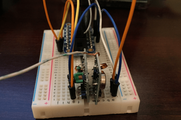
[Tim] decided to use a Raspberry Pi as the brains of the controller. He also purchased a SMAKN 433MHz RF receiver and transmitter for communicating with the wireless outlet switches. The wiring for the modules is pretty simple. There are only four wires. There are power and ground wires for each module. Then the transmitter needs two GPIO pins while the receiver only needs one.
[Tim] began with a fresh installation of Raspbian. He then installed Wiring Pi, which gives you the ability to interface with the GPIO pins in a way that is similar to Arduino. He also installed Apache and PHP to create a web interface for switching the outlets. The last step was to write some custom software. The software included a script that allowed [Tim] to sniff out the controls of his RF remote. The correct codes are entered into the “toggle.php” file, and everything is set. All [Tim] has to do now is browse to his Pi’s web server and click a button. All of the custom code is available via git.