A ‘meter is one of the most important tools on any electronics bench. After you’ve exhausted your five senses trying to figure out what’s happening in a circuit, firing up the old ‘meter is usually the next step. Meters are largely digital nowadays, but their analog ancestors are still widely available. We have a chemist and inventor named [Edward Weston] to thank for the portability and ubiquity of DC measuring equipment.
After immigrating to the United States from England with the degree in medicine his parents wanted him to earn, [Edward Weston] asserted that he was more interested in chemistry. His career began in electroplating, where he soon realized that he needed a reliable, constant current source to do quality plating. This intense interest in power generation led him to develop a saturated cadmium cell, which is known as the Weston cell. Its chemistry produces a voltage stable enough to be used for meter calibration. The Weston cell is also good for making EMF determinations.
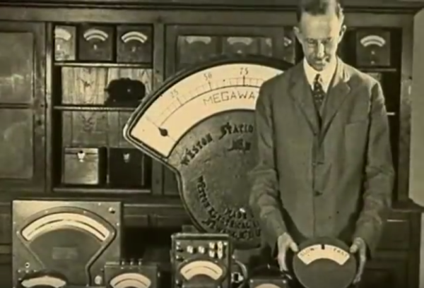
Within a few years, he co-founded the Weston Electrical Instrument Corporation. The company produced several types of meters along with transformers and transducers known for their portability and accuracy. In 1920, [Weston & Co.] created this 1920 educational film in cooperation with the United States Navy as part of a series on the principles of electricity.
The viewer is invited to consider the importance of measurement to civilization, most notably those fundamental measurements of length, mass, and time. [Weston] positions his electrical measuring instruments at this level, touting them as the international favorite. We get the full tour of a Weston meter, from the magnet treated for permanence to the specially designed pole pieces that correctly distribute lines of magnetic force. What education film about electromagnetism would be complete without an iron filings demonstration? This one definitely delivers.
Continue reading “Retrotechtacular: Weston Electrical Instruments”
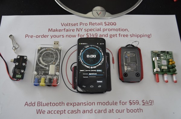
 [Tom] told us that the team is currently redesigning their hardware. The next generation prototype board with more protection can be seen in the far right of the top photo. He also mentioned that they’re shooting for 5 digits of accuracy, placing them on par with many bench scopes. We’re skeptical to say the least about 5 digits, but the team is definitely putting their all into this product. We’ll wait until the Kickstarter backers start getting their final devices to see if Voltset is everything it’s cracked up to be.