Measuring the body’s electrical signals is a neat trick… if you can get your equipment dialed in enough to establish dependable measurements. The technique is called Surface ElectroMyography (SEMG) though you’ll hear many call this ECG. They’re essentially the same technology; the Electro CardioGraph instruments monitor the activity of the heart while SEMG Instruments monitor electrical signals used to control other muscles. Both types of hardware amount to an instrumentation type amplifier and some form of I/O or display.
This topic has been in my back pocket for many months now. Back in May we Hackaday’ites descended on New York City for the Disrupt NY Hackathon event. We arrived a day or so early so that we might better peruse the Korean BBQ joints and check out the other electronics that NY has to offer. On Saturday we gathered around, each shouting out the size of his or her t-shirt preference as we covered up our black Hackaday logo tees with maroon maroon ones (sporting the Hackaday logo of course) for a 24-hour craze of hardware hacking.


There were two individuals at our tables who were both hacking away on hardware to measure the electrical field produced by the body’s muscles in some form or another. The electrical signals measured from the skin are small, and need careful consideration to measure the signal despite the noise. This is a fun experiment that lets you work with both Instrumentation Amplifiers and OpAmps to achieve a usable signal from the movement of your body.

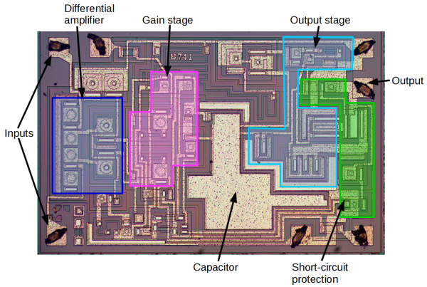
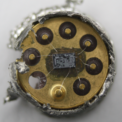 Rather than risk the boiling acid method commonly used to decap epoxy-potted ICs, [Ken] wisely chose a TO-99 can format to attack with a hacksaw. With the die laid bare for his microscope, he was able to locate all the major components and show how each is implemented in silicon. Particularly fascinating is the difference between the construction of NPN and PNP transistors, and the concept of “current mirrors” as constant current sources. And he even whipped up a handy interactive chip viewer – click on something in the die image and find out which component it is on the 741 schematic. Very nice.